

1. Introduction
Many researchers have studied the structures and ferroelectric phase transition of perovskite-type ferroelectrics and bismuth layered structure ferroelectrics (BLSFs) ceramics and thin films because of their good applications and physical properties.1,2) Lanthanum-modified lead zirconate titanate (PLZT) with Zr/Ti ratio of 65/35 and La contents between 5 at% and 14 at% are relaxor ferroelectrics.3,4,5) RFEs are characterized by a frequency dispersion of the complex permittivity, where the temperature of the permittivity maximum shifts to higher temperatures with the increasing of the measurement frequency. RFEs have attracted great attention from the point of view of both fundamental physics and applications, since they exhibit extraordinary electromechanical and dielectric properties.6,7) The degree of relaxor behaviour in the PLZT series is known to increase with the increase of the La content. It is believed that the coupling of the ferroelectrically active oxygen octahedra is broken by the aliovalent La ions and resultant A-site vacancies, which results in the formation of locally polarized regions, instead of a macroscopic transformation into a long-range ordered ferroelectric state.3,4,5,6,7) The Pb1-xLax(Zr1-yTiy)1-x/4O3(PLZT-x/100-y/y) is a member of the perovskite-type oxide materials.8,9,10,11,12,13) The most typical properties of PLZT ceramics with Pb/La ratios (0 < x < 5 %) and Zr/Ti ratios close to 95/5 are strong diffuse antiferroelectric-ferroelectric (AFE-FE) phase transition, exceptionally big thermal hysteresis, and a wide temperature range in which the AFE and FE phases coexist.8,9,10,11) PLZT-x/95/5 undergoes successive phase transitions: at the upper transition temperature (TU) from the cubic (Pm3m) high-temperature paraelectric phase (PE) to the rhombohedral (R3c or R3m) intermediate-temperature ferroelectric phase (FE), and at the lower transition temperature (TL) to the orthorhombic (Pbam) low-temperature antiferroelectric phase (AFE).11) Dielectric constant displays a slightly discontinuous drop at TL and a sharp peak at TU.8,9,10,11) The AFE-FE phase transition points are shifted downwards with increasing La content (0.5 < x < 5 %).8,9,10,11,12,13) The La-doped and Zr/Ti(95/5)-fixed PLZT-x/95/5 ceramic undergoes the following three phase transitions transitions;

Handerek et al.12) reported dielectric, pyroelectric, and thermally stimulated depolarization current investigations for PLZT x/95/5 ceramics for 0.5 < x < 4.0 %. They observed relaxor like dielectric dispersion (10 Hz~104 Hz) at TU and attributed this anomaly behavior to space-charge-induced polarization by mobile ionic defects. In PLZT-x/95/5 (x > 5) ceramics, relatively little has been done to study the diffuse dielectric anomaly below and above the phase transition temperature. Thus, we selected PLZT-8/95/5 ceramics, whose phase transition phenomenon is a smaller research area compared to dielectric phenomenon below and above phase transition temperatures. The purpose of the present study is to explain the dielectric anomaly and the conduction mechanism of PLZT-8/95/5 ceramics by making the complex impedance Cole-Cole plot.
2. Experimental Procedure
A La modified PLZT ceramics (Pb0.92La0.08)(Zr0.95Ti0.05)O3 = PLZT-8/95/5 were prepared by mixing the oxides, PbO (99.9 %), La2O3 (99.9 %), ZrO2 (99.9 %), and TiO2 (99 %) in molar ratio like using the conventional solid state reaction method. The calcinated powder at 900 °C for 4 h was pressed into a molder of sintered at 1,300 °C for 2 h. The X-ray diffraction analysis confirmed that all of the samples used for the measurement were monophasic under the direction limit of the equipment. The samples were electrode with Gold coating. The real and the imaginary capacitances were measured by an SI1260 Impedance analyzer at temperature of 50~550 °C with heating rate of 0.2 °C /min in the frequency range of 1 Hz~1 MHz.
3. Result and Discussion
Fig. 1(a, b) describe a typical temperature dependence of the (a) real ε′ and (b) imaginary dielectric constant ε″in PLZT-8/95/5 ceramics at a temperature range of 30~550 °C. The inserted figures in Fig. 1(a) shows the dielectric dependence of PLZT-8/95/5 ceramics according to temperature for 1 MHz because the dielectric dispersion phenomenon at low frequencies is severe, making it difficult to observe the phase transition anomaly at high temperatures in PLZT-8/95/5 ceramics. High temperature anomaly shows weakly broadening two peaks at TU1 = 179 °C and TU2 = 232 °C. A low temperature anomaly was not observed. We expect that low temperature phase transition of this sample appear under room temperature because this phase transition temperature decreases with increasing La contents.

The values of ε′ and ε″ began to increase about 100 °C, and as the temperature increases above 100 °C there appears an increasingly broader distribution, and the values of ε′ and ε″ increase with decreasing frequency, so-call dielectric dispersion. This conforms to the known fact that ε″ is related to the ionic conductivity σ as ε0ωε″, where ω is the frequency and ε0 is the vacuum permittivity.14) The ε″ increases gradually because the electrical conductivity increases above 100 °C. This may mean that, after the thermally activated migration of the charge carrier, the internal field is built up with the PLZT-8/95/5 ceramic. Thus, the ε′ anomalies near Tc change to a point of inflection due to the rapid increase caused by the electrode surface polarization capacitance, which is much larger than the sample capacitance. This may indicate that there is a coupling between space charge and ferroelectricity.
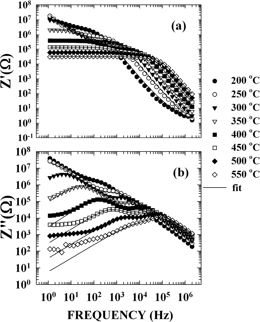
To understand the dielectric dispersion above 100 °C, we carried out a data analysis in the frequency space. Fig. 2(a, b) present the variation of the real (Z′) and the imaginary (Z″) parts of the impedance versus frequency using a double logarithmic scale for several temperatures. The relaxational peak frequency of Z″ moves to a high-frequency region with increasing temperatures. The absolute values of the high-frequency slopes are, in fact, very close to unity and seem to be independent of the temperature. In the low-frequency region, the other relaxational peak frequency of Z″ appeared above 350 °C and rose with the increase in temperature. These two different tendencies in temperature dependence suggest that two dispersion mechanisms may be involved. Considering the existence of two dispersion mechanisms and the bulk (resistance, R1; capacitance, C1) and the grain boundary (resistance, R2; capacitance, C2) of the material, an equivalent circuit can be proposed, as shown in the Fig. 3.

The complex impedance of materials with two independent relaxorscharacterized by relaxation times τ1 (bulk effect) and τ2 (boundary effect) may be written in the superposition of the two Cole-Cole expression14) :
where, ω1 and ω2 are the characteristic angular frequencies determined from relaxation times τ1 and τ2, respectively.
The complex impedance of Eq. (1) may be decomposed into real (Z′) and imaginary (Z″) impedance parts,
The solid lines in Fig. 2(b) are theoretical curves obtained by using Eq. (3). Only the data relative to the imaginary part were used in the fitting. The six parameters, m, n, τ1, τ2, R1 and R2, were then introduced into the real part of the formula to check whether the calculated values are also in agreement with the measured value of Z′. The agreement between the experimental and calculated values for both the real and imaginary parts of the impedance confirms that the model proposed here is pertinent to the description of the diffuse dielectric anomaly of PLZT-8/95/5 above and below the phase transition. The parameters m and n take values over the entire range 0 ≤ m, n ≤ 1 and may be functions of temperature. The fitting leads always to a value of m close to unity and independent of the temperature, shows a very strong variation of the values of exponent n within 0.7 ≤ n ≤ 1. The exponents n and m have no physical significance whatever; they are purely empirical factors to describe the appearance of the experimentally obtained impedance Cole-Cole plot.
The loss peak frequencies, ω1 and ω2, were obtained by fitting the imaginary impedance data to Eq. (3) and the variation of relaxation times τ1 = 1/ω1 and τ2 = 1/ω2 as a function of reciprocal temperature are shown in Fig. 4. Relaxation time (τ2) of low frequency region show two peaks at TU1 = 179 °C and T U2 = 230 °C, and high frequency relaxation time (τ1) was not changed at TU1 and TU2.

The impedace spectra of PLZT ceramics fit well with two relaxation times. This means that there are two relxation time-dependent of impedance mechanisms in the PLZT ceramic. As shown in Fig. 3, the one that contributes to the fast time can be seen as an bulk effect such as mobile ion of the ceramic, and the larger impedance mechanism can be said to show a slow time dependence. Thus, the high frequency component may be due to the ion migration in the bulk, and the low frequency component is interpreted as the formation and migration of ions or surface effect at the grain boundary.
PLZT has a structure of ABO3 perovskite, and Pb2+ and La3+ are engaged in the A-site while Zr4+ and Ti4+ are engaged on the B-site, which is the centre of an octagon made of O2-. It is known that if La3+ were replaced by Pb2+, then there would be a vacancy in the structure to maintain electric neutrality because La3+ has one more atomic value than Pb2+.15,16)
The formula for PLZT is as follows if there is a vacancy at the B-site15,16) :
The formula for PLZT is as follows if there is a vacancy at the A-site [14]:
where, □ is vacancy. In general, it is known that the vacancy would transpire at both the A- and B-sites, while the ratio of the A-site vacancy is increased more if the PbZrO3 ratio is bigger than that of PbTiO3. The impedance relaxations occurring at low frequencies and high temperatures can be related to ionic space-charge carriers, such as the vacancies, ion migration and defects in the bulk, and interfacial polarization located at the grain boundary.
4. Conclusion
The electrical property of the PLZT-8/95/5 ceramic was studied by means of the impedance spectroscopy method in the temperature range from 30 °C to 550 °C. The complex dielectric constant anomalies of the phase transitions were observed near TU1 = 179 °C and TU2 = 230 °C. A remarkable diffuse dielectric constant anomaly behaviour of complex capacitance was found between 100 °C and 600 °C.
The complex impedance spectra below and above TU1 were fitted by the superposition of two Cole-Cole types of relaxations. We have found two different conduction mechanisms, which have different relaxation times τ1 in the high frequency and τ2 in the low frequency regions. The complex dielectric constant dispersion is significant at the temperature range in which the contributions of the two conduction mechanisms are comparable to each other. The fast component in the higher frequency region may be due to the ion migration in the bulk, and the slow component in the lower frequency region is interpreted as the formation and migration of ions at the grain boundary or electrode/crystal interfacial polarization.
