

1. Introduction
2. Materials and Experiments
2.1. Structures design and fabrication
2.2. Characterization
3. Results
4. Conclusions
1. Introduction
Trapping cells are used in various applications like microfluidic systems;1) tissue engineering of cellular patterning;2) photometric trapping of solar cells3) and used in counting the white blood cells.4) Several methods can be used to trap the biological cells5) and cancer cells6,7) However, some method used for cancer treatment using near-infrared laser responsive bullets as multifunctional nano-drug stages through a three-dimensional 3D printing handle as an image-guided flexible chemo photothermal cancer treatment stage.8) But here we will employ magnetic structures to achieve that.
The magnetic particles and magnetic structures have a variety of applications, including drug delivery,9) magnetic resonance imaging,10,11) biosensors and actuators.12) Magnetic structures can be used to trap cells or to control the arrangement of their locations. This technique can turn the trapping on or off to allow cells to be released from their locations.
Numerous fabrication techniques were used to fabricate the magnetic structures such as photolithography,13) EBL,14,15) and X-ray lithography.16)
Several studies have shown that cell trapping by magnetic structures was performed. These magnetic structures were designed with different shapes such as rings, squares and rectangular and with various magnetic materials (Ni, Nife and Fe2O3)17,18,19) for trapping cells.
Cancer is defined as the abnormal growth of cells inside the human body, where cells grow and divide normally in the human body in normal cases.20) In the case of cancer, it is an abnormal increase in cell division in large numbers in one place in the body or spread to multiple places. Most types of cancers are in the form of tumours that cause damage and imbalance in the functions of the body’s organs through blockage and pressure on the various places of the body. One of the most important reasons is a change in the DNA strand resulting from a variety of factors, some known and some unknown exposure to for example radiation, chemicals, or high-pressure power lines of electricity may be one of the reasons for affecting DNA and causing genetic mutations in it to form a new protein and split dramatically and uncontrollably.21)
There are many types of cancers, including colon, stomach, lung, and breast cancer, the subject of current research, breast cancer in women and men remains the most important type of cancer, that causes many deaths all over the world.22)
In this project, we present a method for trapping cancer cells using micro-magnetic structures that have few side effects and allow the trap to be on and off remotely. This project aims to contribute towards the development of the technique of magnetic trapping of cancer cells.
2. Materials and Experiments
2.1. Structures design and fabrication
Raith software was used to design two types of magnetic structures: rectangular wire and zig-zagged wire on a silicon substrate.
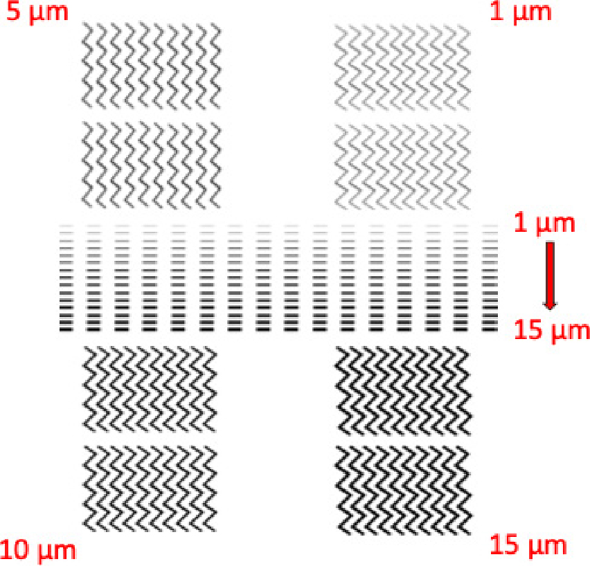
The first structure was designed with narrow, tapered ends for trapping. The length of each rectangular wire was 150 µm while the wire widths were in the range of 1 to 15 µm. These structures were designed and patterned into 16 columns, each column containing 15 wires.
The second design of the magnetic structure was the zig-zagged wire. Each straight line of zig-zagged wire was 150 µm in length and the width was 1, 5, 10 and 15 µm the angle between each two was 90° and the radius of the curve at the corners was 10 µm. Therefore, at these curves, the domain walls are formed, therefore, it will be the trapping positions. Four arrays of zig-zagged magnetic structures were fabricated and each array contained two rows with 10 zig-zagged wires. These zig-zagged structures were placed around the rectangular wire arrays as shown in Fig. 1.
These designs were transferred using EBL on a layer of polymethyl methacrylate (PMMA) that was added to a silicon substrate. The PMMA layer was subsequently exposed to an electron beam and then followed by a development step using an appropriate solvent to remove the most soluble polymer (exposed areas).
The magnetic layer of 30 nm permalloy (Ni80Fe20) was deposited using the thermal evaporator after the development step to create the structure directly on a silicon substrate. Finally, to obtain only the desired magnetic structure on a silicon substrate, PMMA lift-off was implemented.
The permalloy was selected depending on its magnetic properties because it has zero-magnetocrystalline so the shape of the magnetic structure is sensitive to the direction of the applied magnetic field,23) therefore, the magnetic response of the structure is higher along the long axis and steadily increase with increasing the aspect ratio of the structure.
After creating the magnetic structures, a plasma-enhanced chemical vapour deposition (PECVD) was used to deposit 30 nm of silicon nitride on the magnetic structure as an antifouling and for its ability to resist acid corrosion and oxidation.
A spin coating technique was used to deposit a thin layer of polyethylene glycol on the magnetic structures and substrate surface to prevent protein adsorption and then to reduce the adhesion of trapping cancer cells to the surface. polyethylene glycol is a non-toxic material24) that can save the viability of the trapped cancer cell.
The Dulbecco’s modified Eagle’s medium (DMEM) (Lonza BioWhittaker®) have been used to culture the MDA-MB-231 triple-negative breast cancer cells in T-75 flasks25) and then incubation at 37°C in carbon dioxide (CO2) incubators are a very important instrument to provide the normal environment in the biological laboratories, to incubate tissue cultures as the same traditional temperature at 37°C and pH of 7.2 to 7.5 (Fig. 2).26)
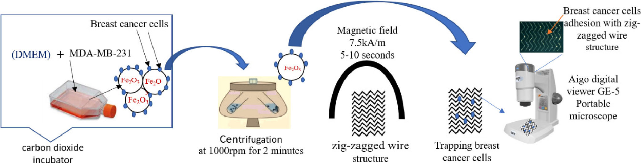
A T-75 flask was used to culture the cancer cell before 24 h make procedure. A concentration of 0.1 mg/ml of iron (III) oxide nanobeads purchased from Sigma-Aldrich was added (see Fig. 2), with 10 % foetal bovine serum (FBS) to supplement the medium for cell culture growth and 1 % penicillin and streptomycin, to prevent the bacterial contamination of cell cultures.27)
Moreover, arrays of rectangular magnetic wires with dimensions of 100 by 10 µm with the same previous thickness were fabricated using an LDW technique. A thin film of permalloy was deposited on glass substrates then the focusing laser beam was used to remove undesirable parts of the thin film with a one-step process. The spaces between each element were 40 µm vertically and horizontally as shown in Fig. 3.

Fig. 4 explains the process steps of each technique used to pattern the magnetic structures.

2.2. Characterization
The magnetic properties of the magnetic structures were tested using the magneto-optic Kerr effect system (MOKE). The MOKE system detects the changes in the intensity of the reflected polarized light from the magnetic surface (structures, for more details about MOKE system see references.28,29)
2.2.1. Cell adhesion test
Five different ways are employed to test the cell adhesion as shown in the Table 1.
Table 1.
Five different types to test cell adhesion.
10 of the substrates of five types were used for cell adhesion testing (two substrates for each type) and were sterilized with 70 % ethanol for 10 min before the test. Then placed in a phosphate buffer solution (PBS) for 10 min30) and then transferred to a Petri dish containing 6 wells, and then experiment with the cells that were grown in flask T-75, cells were incubated for 2 h and observed under a portable microscope type (Aigo Digital Viener GE-5).31)
The images were taken using the camera built into the portable microscope. Two images were taken for each substrate, that is, 4 images for each type of surface.
3. Results
Fig. 5 shows the optical microscopy images of magnetic structures patterned by EBL. The images show the design and explain the pheasant of the wire widths for each structure (rectangular and zigzag). For the zig-zag design, the differences between each width are more pronounced than in the rectangular structure because we fabricated the widths in of 5 µm increments each, while in the rectangular there are 15 widths increments of only 1 µm.

Fig. 6 shows the optical microscopy images of rectangular magnetic wires patterned by LDW.

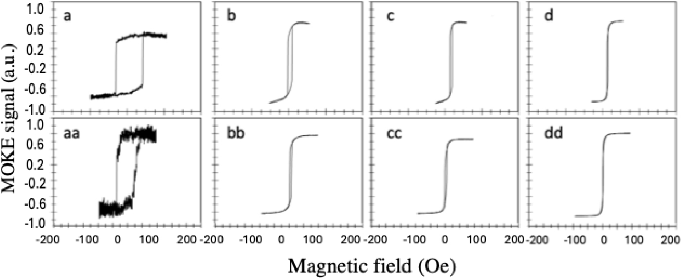
The magnetic properties were tested before and after adding a layer of silicon nitride for all samples using MOKE system. Fig. 7 shows the hysteresis loops of EBL fabricated rectangular wires of the width of 1 µm to 15 µm along the long axis (the easy axis) before adding the layer of silicon nitride. The coercivity decreased from 106 Oe for the wire of 1 µm width to just 19 Oe for the wire of 15 µm width. The coercivity is inversely proportional to the width of the wire because the wider wire contains magnetic domains more than the narrow wire therefore it will be difficult to keep the alignment of the domains.
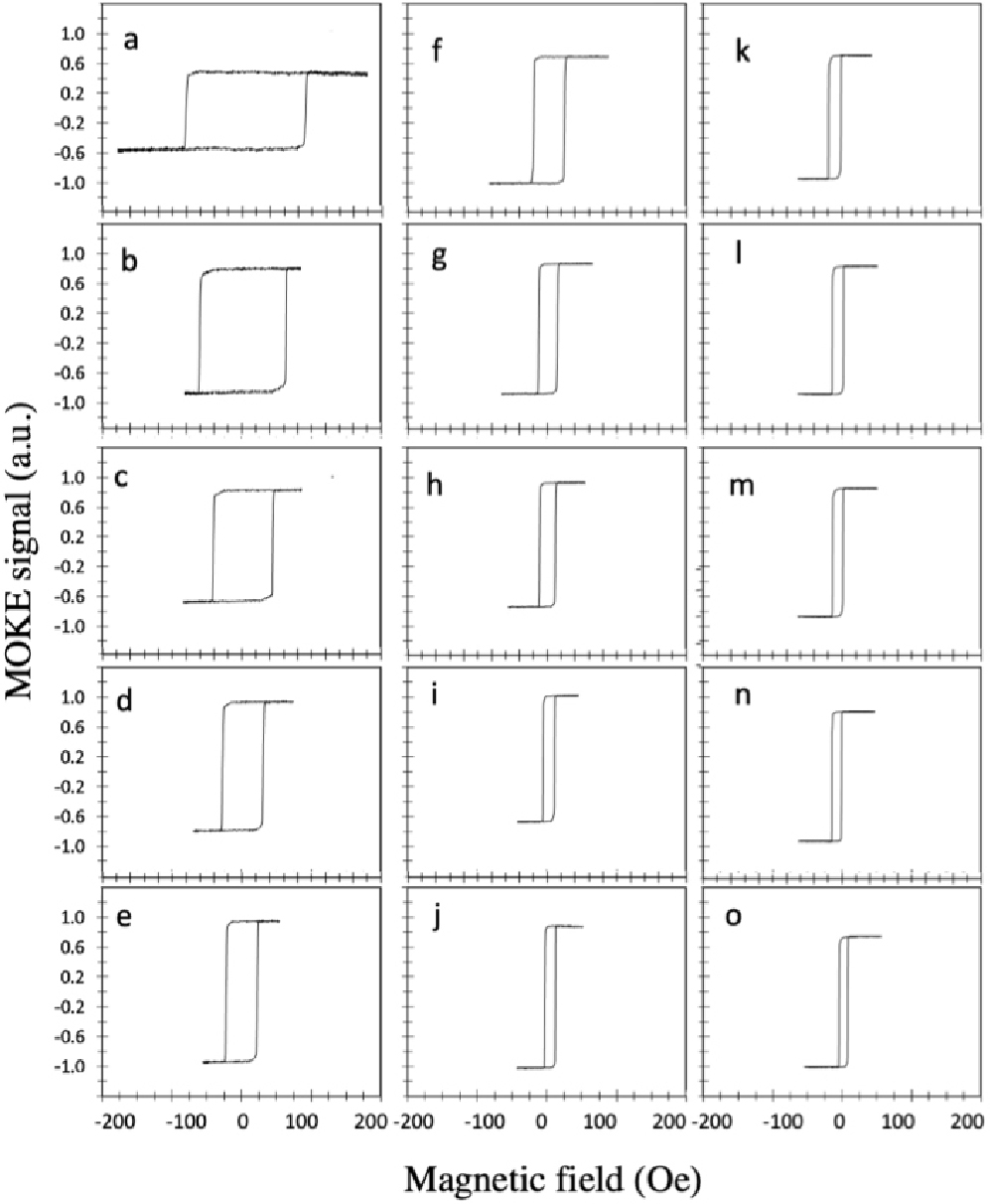
Fig. 7.
MOKE hysteresis loops of EBL fabricated rectangular wires of width (a) 1 µm, (b) 2 µm, (c) 3 µm, (d) 4 µm, (e) 5 µm. (e) 5 µm, (f) 6 µm, (g) 7 µm, (h) 8 µm, (i) 9 µm, (j) 10 µm, (k), 11 µm, (l) 12 µm, (m) 13 µm, (n) 14 µm and (o) 15 µm measured along easy axis (long axis) before adding silicon nitride layer.
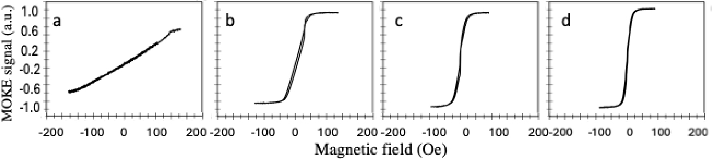
However, the hysteresis loops of magnetic wires measured show it has very small coercivity along the hard axis (short axis). Therefore, it will be difficult for fabricated structures to retain their magnetism along the short axis as shown in Fig. 8.
The magnetic responses of zigzag magnetic structures were also tested using the MOKE system along the horizontal and vertical axes. Fig. 9 shows the approximate similarity of hysteresis loops measured along the two axes because the zig-zagged structures are diagonal in both directions. However, the coercivity of wires of widths 5, 10 and 15 µm respectively are quite low, but the wire with width 1 µm showed higher coercivity (74 Oe for the horizontal axis and 65 Oe for the vertical axis respectively).
After adding a 30 nm of silicon nitride above the structures, the magnetic properties were tested again using MOKE system to study silicon nitride effect on the magnetic responses of the structures. The results did not show any significant changes in magnetic responses as shown in the hysteresis loops in the Figs. 10 and 11 comparing with the hysteresis loops in Figs. 7 and 9. This indicates the possibility of using silicon nitride as a protective layer.


The images in Fig. 12 show the selection of cell adhesion to different surfaces according to the types and concentrations mentioned in Table 1, which formed the appropriate surface for adhesion of breast cancer cells. The pictures showed numbers marked against them, as in diagram Fig. 13.

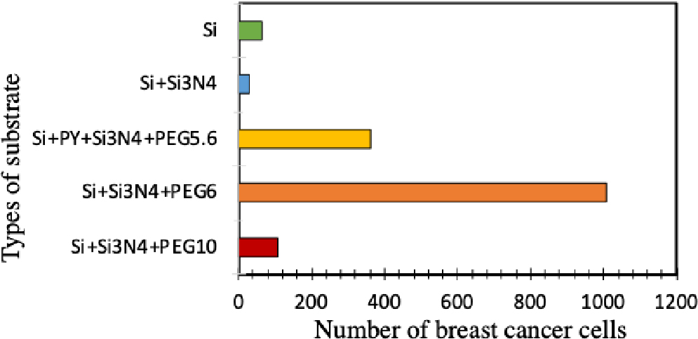
Fig. 13.
Average number of cells for each substrate, as it relied on the image J. program to calculate the number of cells on each imaged slide in Fig. 12.
The results showed that the best adhesion of cells to the surface of Si + Si3N4 + PEG followed by Si + Py + Si3N4 + PEG concentration of 5-6 with permalloy indicates that this layer affected silicon nitride in the presence of polyethylene glycol (PEG).
The lowest level of adhesion appeared with silicon substrate after nitrite deposition.
The average number of cells) Fig. 12 (surface type was determined by image analysis using image J program during cell adhesion.
The first experiment to trap tumour cells loaded with magnetic nanobeads that were explained previously did not achieve success possibly because of the short time of leaving the cancer cells incubating with the nanobeads (1 h only). This short time is not enough for cancer cells for capturing sufficient nanobeads. Accordingly, the incubation time was extended to 24 h, but that did not provide a better result.
To check whether the magnetic structures can pick up the magnetic nanobeads, another experiment was performed. This test was implemented using only the magnetic nanobeads. However, few beads were trapped by the structures as shown in Fig. 14 that also showed the randomly distribution of nanobeads on the magnetic structures.

For studying the effect of silicon nitride on the magnetic structures, the experiment was repeated without depositing any coating. This attempt did not achieve trapping for cancer cells, but it captured more nanobeads as shown in Fig. 15.
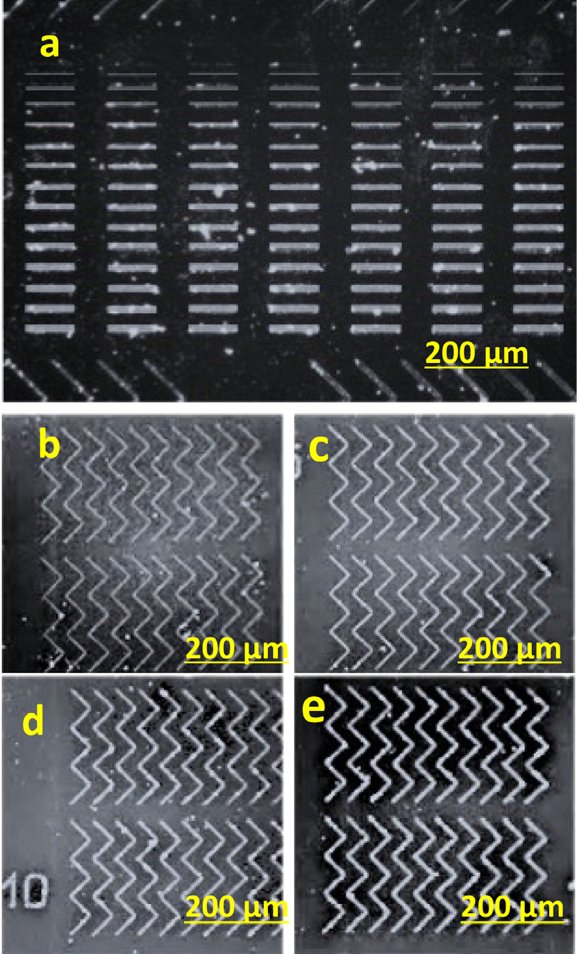
Fig. 15.
Optical microscopy images of (a) rectangular wires of 150 µm in length with a width range of 1 to 15 µm, (b) zigzag wire with width of 1 µm, (c) zigzag wire with width of 5 µm, (d) zigzag wire with width of 10 µm, (e) zigzag wire with width of 15 µm fabricated using EBL on silicon substrates without depositing any coating for trapping cancer cell.
One possible reason the cells are not being trapped is that the beads are too small relative to the size of the cells. The nanobead might not provide enough force to anchor the cells to the structures. The incubation time of the substrates with the loaded cells might have contributed to cells not being trapped too as cells might not have enough time to settle towards the structures. The time should be increased in the future to at least 45 min or 1 h. Another factor that might have caused the lack of trapping could be the concentration of nanobeads, which may not be high enough to have the cells take up enough. This can be another area to investigate. The clumping up of the beads could have reduced the available amount for the cells to take up, adding to the problem.
4. Conclusions
The micromagnetic structures were designed and fabricated using two fabrication techniques EBL and LDW. Rectangular wires with range of widths and zigzag with width were 1, 5, 10, and 15 µm were patterned on a silicon substrate. These structures showed good responses to the applied magnetic field despite adding layers of silicon nitride and polyethylene glycol. The results showed that the best adhesion of cells to the surface of Si + Si3N4 + PEG followed by Si + Py + Si3N4 + PEG concentration of 5-6 with permalloy indicates that this layer affected silicon nitride in the presence of polyethylene glycol (PEG). The cells were not trapped possibly due to the small size of beads compared to the size of cells. Next attempts will deal with different (larger) sizes of nanobeads.
