

1. Introduction
2. Various Types of Slipchip
2.1. Slider-manipulation-type Slipchip
2.2. Linear slider-manipulation-type Slipchip
2.3. Circular slider-manipulation-type Slipchip
3. Dry Sample Preservation in Slipchip Materials
4. Conclusion
1. Introduction
Over the past few decades, owing to the occurrence of various viral pandemics such as the influenza A virus subtype (H1N1), severe acute respiratory syndrome (SARS), Ebola, and the COVID-19, a fast and massively parallel diagnostic technique is urgently needed to rapidly screen patients. Lab-on-chip (LOC) systems allow for reduced consumption of fluid volumes during screening (less waste, lower reagents costs, and smaller required sample volumes), and they have advantages such as faster analysis and response times (high surface-volume ratio and small heat capacities), high-throughput analysis (device compactness), lower fabrication costs (through mass production),1) which makes them ideal to be deployed for quick screening. In addition, the automation of LOC devices does not require skilled workers, and the absence of error-prone manual laboratory protocols ensures that the results of these assays are consistent.2) LOC systems can integrate different biochemical processes, including mixing,3,4) cell separation,5,6) valving,7,8,9) metering,10) pumping,11,12) surface treatment,13) and gene amplification,14,15,16) which can make the device compact but requires smart design. In multistep reactions, small-volume inputs, for example at the nanoliter or microliter scale, need to be controlled for mixing, dilution, and other operations. In this regard, Slipchip is an attractive platform for building multistep capabilities.17) It offers the benefits of a miniaturized platform such as small reagent volume and high relative concentrations of analytes.18,19,20) In addition, Slipchip devices can be operated easily by simply slipping the slider to perform complex fluidic manipulations. Many researchers have extensively studied the design, fabrication, and testing processes of Slipchip. The existing literature on Slipchip mainly focuses on a specific design or topic, such as nanoliter-scale mixing,17) serial dilution nanoliter arrays,21) AST,22) bacterial screening,23) replica microbial cultures,24) and flow manipulation and control.25) A comprehensive review is needed to provide an overall view of the Slipchip system to readers, especially considering the recent rapid advancement of the Slipchip device field. This is especially important for those who would like to be abreast of the latest developments in the LOC field and gain a holistic understanding of the system.
2. Various Types of Slipchip
2.1. Slider-manipulation-type Slipchip
This linear Slipchip does not manipulate droplets. Instead, it is used to inject different reagents by controlling the slider position. Fig. 1 shows the slider-manipulation-type Slipchip—a paper-based analytical device developed by Verma et al.26) that can be used to perform an enzyme-linked immunosorbent assay (ELISA). The device consists of two parts: a sliding strip (containing the active sensing area) and a structure encircling the sliding strip (that keeps saved reagents, which is buffers, antibodies, and enzymatic substrate, and allocates fluid). Running an ELISA, first involves adding a sample (e.g., blood) and water, second acting the sliding strip at intended times, and third must assay the resulting color in the sensing area optically or use a flatbed scanner. This concrete of Slipchip is demonstrated to detect C-reactive protein (CRP), which is a biomarker of pelvic inflammatory disease, neonatal sepsis, and inflammatory bowel disorders, in the density range of 1~100 ng/mL in 1,000-fold diluted blood (1~100 µg/mL in the original blood). Additional, 10 ng/mL (for pelvic inflammatory disease and neonatal sepsis) were the accuracy of it is 89 % and 30 ng/mL (for inflammatory bowel diseases) CRP in 1,000-fold diluted blood were the accuracy of it is 83 %. This device can be utilized as portion of a kit in resource-limited settings (including a pre-filled tube, the device, a fixed-volume capillary, a syringe, and a dropper); it costs ~$0.50/unit when produced on a large scale (>100,000 devices/week). In addition, the kit has the technical characteristics needed to use it as a pre-screening implement, when united with a different data such as clinical symptoms and patient history.26) The operation process of this Slipchip is shown in Fig. 1(C): i) When the sliding strip is in position 1, a sample is added to the inlet and washed with water. ii) The sliding strip is moved to position 2 and water is added through the inlet to dissolve the stored detection antibodies and buffer, as well as to wash off excess detection antibodies. iii) The sliding strip is moved to position 3 and water is added through the inlet to dissolve the stored substrate and buffer, as well as to wash off excess substrate. iv) The sliding strip is removed from the device to analyze the results visually or by using a desktop scanner. Fig. 1(D) depicts the relevant detection mechanism, and the steps are analogous to those in upcoming sections. Depending on the slip direction, the slider-manipulation-type Slipchip can be classified as linear and circular. The slider in linear slider-manipulation-type Slipchips usually moves linearly while that in circular slider-manipulation-type Slipchips moves circularly.
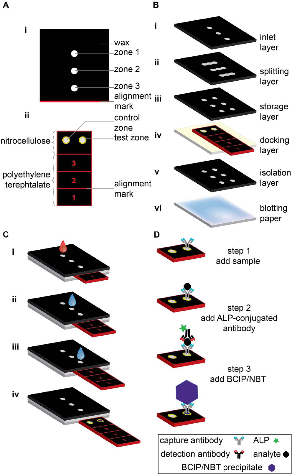
Fig. 1.
Schematic illustration of slider-manipulation-type Slipchip. (A) Top view of (i) functional dock, and (ii) sliding strip showing various parts of each component. (B) Components of the slider-manipulation-type Slipchip; each layer is glued using double-sided tape and has holes that connect the fluidic channels. (C) Slipchip operation. (D) Operating mechanism of operation of the slider-manipulation-type Slipchip device; the steps are analogous to those in part C.26)
2.2. Linear slider-manipulation-type Slipchip
A linear slider-manipulation-type Slipchip usually contains a slider that slips relative to a fixed plate or housing. By slipping the slider, the mixing well can be connected to the same carrier well multiple times when the reagent volumes of the two wells are equal or to different carrier wells that have various volumes chronologically. Fig. 2 shows a multistep Slipchip microfluidic device developed by Yu et al.21) This device can generate serial dilution nanoliter arrays with high throughput by using a series of simple sliding motions [69]. The dilution ratio can be predetermined precisely from the volumes of the mother and daughter microwells. Using 64 wells for respectively dilution and fewer than 600 wells, the continuous dilution Slipchip can gain a theoretical quantification dynamic range spanning 7 orders of magnitude.
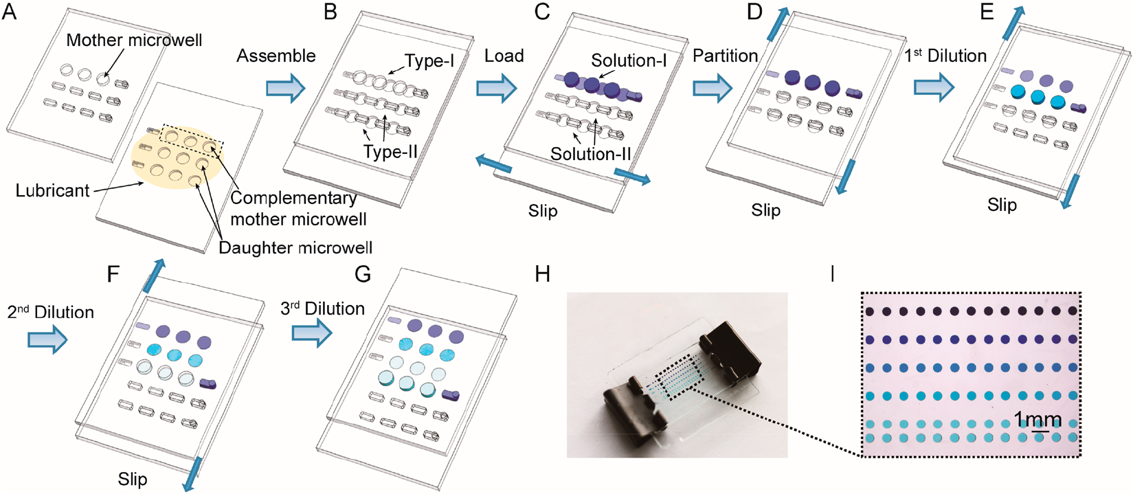
Fig. 2.
Schematic drawings of Slipchip operations: (A) Top and bottom plates of Slipchip device, (B) Slipchip assembly by partially overlapping the wells and ducts on the contacting surfaces of two plates, (C) introduction of original solution (Solution-I) and dilution buffer (Solution-II) into Type-I and Type-II channels, respectively, (D) top plate moved to the right to form isolated reaction partitions, I top plate moved downward to perform the 1st dilution step, (F) top plate moved downward for the 2nd time to perform the 2nd dilution step, (G) top plate moved downward for the 3rd time to separate the wells on the top layer from those on the bottom layer, (H) photo of a four-step Slipchip, and (I) magnified photo showing the serial dilution pattern of blue dye.21)
Fig. 3 shows a schematic of a microfluidic digital RPA Slipchip for simultaneous initiation of >1,000 nL-scale RPA reactions by adding a chemical initiator to each reaction compartment by means of a simple slipping step after instrument-free pipette loading:27) (A) Top plate of the microfluidic digital RPA Slipchip; a zoomed-in schematic drawing shows the geometry of the type I, type II, and satellite wells. (B) Bottom plate of the microfluidic digital RPA Slipchip. (C) At the type I wells, the assembly of top and bottom plates to connect a first serial fluidic path. (D) Reaction mixture 1 (red) at loading of the first reagent. (E) Damage of the first fluidic path is caused by slip-ping and the loaded reagent is compartmentalized. Simultaneously, when the type II wells connect each other, second fluidic path is formed. The reaction mixture 2 (light blue), which is the second reagent, is loaded through a second inlet. (F) Reaction mixture 2 into the type II wells are compart-mentalized by a second slipping step. As a result, it overlaps the type II wells with the type I wells. The two reagents are mixed within the reaction compartments. (G) For size comparison, the entire digital RPA Slipchip is showed next to a U.S. quarter. (H-J) Food dyes are loaded into the Slipchip to demonstrate the loading and mixing processes. (H) Control 2 (no template)’s photograph, which is magnified view of the type II wells loaded with blue food dye. (I) Magnified view of the reaction wells (overlapping type I and type II wells) including mixed orange and blue food dyes (green). (J) Enlarged view of the type I wells for control 1 (no magnesium acetate) loaded with orange food dye. (K-N) Experiments with food dyes for demonstrating the procedures described in panels D-F.

In the digital LAMP area, Slipchip offers the advantage of good tolerance to reaction temperature and time. This is extremely useful for performing diagnostics under resource-limited settings in the absence of sophisticated equipment and expertise. Under these conditions, one may anticipate a slight error in Celsius temperature, utilizing non-quantitative user electronic devices like cell phones, and changes in analysis time because of the operator error.28) Although several robust qualitative tests, such as home pregnancy tests, are already compatible with the resource-limited settings, Slipchip is suitable for quantitative assays under such settings. Similar to the above digital RPA and LAMP reaction, digital PCR can be applied in the Slipchip domain with advantages such as simplicity, low cost, and robustness. Fig. 4 presents a sketch of the digital PCR Slipchip device developed by Shen et al.29) In this device, the fluidic path for introducing the sample combined with the PCR mixture is formed using the elongated wells in the two plates of the Slipchip designed to overlap during sample loading. This fluidic path is disrupted by simply slipping the two plates to remove the overlap among the wells and bring each well in contact with a reservoir preloaded with oil to generate 1,280 reaction compartments (2.6 nL each) simultaneously. After thermal cycling, the presence of nucleic acid is detected by using end-point fluorescence. Digital PCR on the Slipchip was tested quantitatively by using the genomic DNA of Staphylococcus aureus. As the concentration of the template DNA in the reaction mixture decreased due to dilution, the fraction of positive wells decreased, as expected based on statistical analysis. During the experiments, the contamination was not observed. To count nucleic acids, it offers a brief strategy by utilizing PCR. In research applications, it may be helpful in case of the single-cell analysis, prenatal diagnostics, and point-of-care diagnostics. So, in resource-constrained areas, this device is anticipated to be useful for diagnostics after integration about the isothermal nucleic acid amplification technologies and a visual readout system.29)
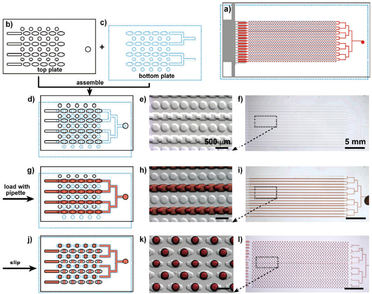
Fig. 4.
Schematic drawing and bright-field images showing the design and mechanism of Slipchip for digital PCR. The top plate is outlined with a black solid line, bottom plate is outlined with a blue dotted line, and the red color represents the sample. a) Schematic drawing shows the design of the entire assembled Slipchip for digital PCR after slipping. b) Schematic drawing of a part of the top plate. c) Schematic drawing of a part of the bottom plate. d-f) Slipchip was assembled such that the elongated wells in the top and bottom plates overlapped to form a continuous fluidic path. g-i) Aqueous reagent (red) was injected into Slipchip, and it filled the chip through the connected elongated wells. j-l) The bottom plate was slipped relative to the top plate such that the fluidic path was disrupted; the circular wells were overlaid with the elongated wells, and aqueous droplets were formed in each compartment. d, g, j) Schematic of the Slipchip; e, h, k) magnified microphotographs of the Slipchip; and f, i, l) microphotographs of entire Slipchip.29)
2.3. Circular slider-manipulation-type Slipchip
A circular Slipchip usually contains a slider that rotates relative to another fixed plate. By rotating the slider, the mixing well can be connected to the carrier well. Fig. 5 shows the rotate-react Slipchip developed by Xia et al.30) for simultaneous visual detection of multiple bacterial pathogens in the loop-mediated isothermal amplification (LAMP) reaction. This Slipchip system consists of two round PDMS-glass hybrid chips that are assembled coaxially by using a plastic screw-nut suite. After sample loading, one-step rotation allows for immediate mixing and reaction of multiple bacterial samples with the LAMP reagents on the chip.

Fig. 5.
Sketch and operation of the circular Slipchip (A) Design and fabrication; after plasma bonding, a screw-nut suite was used to assemble the upper and lower chips to form the final chip. (B) Magnified view showing the one-step rotational slipping operation. (C) Step-by-step mixing of a yellow and a blue food dye on the chip. A piece of white filter paper was placed underneath the chip for visualizing the food dyes.30)
A home-built Peltier heating device was used in conjunction with the aforementioned Slipchip device and an advanced RISC machines (ARM) processor to implement isothermal control (Fig. 6). An about five-times fluorescent signal-to-noise ratio and a detection limit of 7.2 copies/µL genomic DNA were identifed under the optimized LAMP conditions. Moreover, with a success rate of 100 %, five digestive bacterial pathogens (Bacillus cereus, Escherichia coli, Salmonella enterica, Vibrio fluvialis, and Vibrio parahaemolyticus) were confirmed visually by utilizing the setted method in 60 min. This Slipchip is a rapid, simple-to-use, and cost-effective solution for detecting pathogenic bacteria, and it has strong potential for use in clinical diagnosis, especially in resource-constrained areas.30)

Fig. 6.
On-chip simultaneous LAMP detection of multiple bacterial strains, including Bacillus cereus, Escherichia coli, Salmonella enterica, Vibrio fluvialis, and Vibrio parahaemolyticus. (A) Photograph of custom-built Peltier heater housing an RnR-Slipchip. (B) Fluorescence photograph of detection results obtained using the RnR-Slipchip under a UV flashlight in the dark. (C) Quantitative analysis of detection results. The green color denotes positive results with the respective templates, and the orange color denotes negative controls without any template. (D) Gel electrophoresis test of LAMP products. Lane M: 100 bp ladder plus. Lanes 1-2: Negative and positive results of Bacillus cereus. Lanes 3-4: Negative and positive results of Escherichia coli. Lanes 5-6: Negative and positive results of Salmonella enterica. Lanes 7-8: Negative and positive results of Vibrio fluvialis. Lanes 9-10: Negative and positive results of Vibrio parahaemolyticus.30)
3. Dry Sample Preservation in Slipchip Materials
Slipchip devices are usually used to perform biological tests. To remote bio surveillance, medical analysis, and storage, long-term sample stabilization is important. But, within biospecimens, the current technique for transmitting remotely gained samples depended on the expensive “cold chain” to maintain analytes. However, for biological reagents, storage is problematic, especially at room temperature. Dry preservation can stabilize reagents at room temperature, which can reduce the cost of Slipchip systems.
Fig. 7 shows a Slipchip device developed by Begolo et al.31) that incorporates chemical stabilization matrices for the dry preservation of biological specimens at room temperature. Their approach involves the use of microfluidics to preserve samples in the dry state with stabilization matrices, which have been developed by other researchers and are based on the self-preservation chemistries found in nature. The Slipchip-based device leads beginners to conserve samples by being given the three steps: (first) putting a sample at the entrance, (second) shutting down the lid, (third) slipping one layer of the device. The device carries out self-filling, and the samples are dried by a pre-loaded desiccant. Later, for assay in a laboratory, specimens can be rehydrated and retrieved. This device is portable, small, and self-fitted. Thus, even in resource-constrained settings, untrained users can transmit and exploit. The operational process of this device is as follows: First, the Slipchip is loaded, and the colored liquid occupies the liquid channel [Fig. 7(A)]. Second, the chip is slipped until the dashed line matches the middle marker line, which disconnects the wells and allows vapor contact between the sample and desiccant (black) [Fig. 7(B)]. The membrane (yellow part) separates the desiccant and the liquid to prevent liquid contact while allowing vapor contact. Fig. 7(C) shows the drying process, wherein the amount of colored liquid is reduced owing to evaporation. In Fig. 7(D), sample drying is complete, and now the sample will remain stable at room temperature, which simplifies its storage and device transportation. Fig. 7(E) shows the fraction of the wells containing liquid over time in a representative device. This Slipchip has been integrated with a plasma filtration module and validated by testing the stability of purified RNA solutions. These features and the modularity of this platform (which facilitates integration and simplifies operation) can be applied to other microfluidic devices apart from the aforementioned application. As the field of stabilization matrices evolves, Slipchip devices will be useful for facilitating cost-effective remote analysis and biosurveillance while opening up new opportunities in diagnostics, drug development, and other medical fields.31)

Fig. 7.
Overview of slip-initiated drying. (A) A photograph (top) and schematic drawing (bottom) showing the device after loading. (B) A photograph and schematic drawing of the device once it has been slipped. The slip disconnects the wells and allows vapor contact between the sample and desiccant (black). Evaporation starts with the nucleation of an air bubble in each well. (C) A photograph and schematic drawing showing the drying process. The bubbles grow owing to progressive water loss due to evaporation. (D) A photograph and schematic drawing of the device once drying is complete and sample is stabilized (green sample residuals are visible in the wells). (E) Plot showing the fraction of the wells containing liquid over time in a representative device.31)
4. Conclusion
Slipchip devices allow users to perform repeated and complete droplet transfers, thereby facilitating the implementation of multistep processes with the option of retrieving the final products. Importantly, device operation does not require special equipment, which makes it an attractive option for many applications. Given the high performance of this multistep device, it is well-suited for single-cell analyses or studies involving small numbers of cells. Other features of the multistep device that are favorable from the perspective of biological studies include its optical clarity for high-resolution imaging of loaded specimens and thin construction for rapid and uniform temperature control, including freezing and thawing.
In digital RPA, LAMP and PCR, Slipchip devices can be used to generate serially diluted nanoliter arrays with simple multistep slipping operations. The devices do not require cumbersome manual pipetting steps or complex fluidic handling systems. Moreover, they can provide precise dilution ratios by controlling the fluidic volumes in the mother and daughter microwells. Over an extensive dynamic range, these devices can be performed assays with considerable fewer reaction compartments comparing about those generated with single-volume partitions. When performing diagnostics in resource-limited settings, one may encounter the lack of sophisticated equipment and expertise. One can anticipate a change in centigrade temperature under these conditions. Because some cases, such as cell phones, can is non-quantitative consumer electronic devices, and then it can produce operator error. Already, a few cases are compatible with resource-constrained settings like robust qualitative tests, which is home pregnancy tests. But the Slipchip is appropriate for quantitative analysis. Moreover, Slipchip offers advantages such as good tolerance to reaction temperature, time, and imaging conditions. Slipchip has great potential for use in high-throughput, single-cell, and single-molecule analyses. However, highly integrated system functions remain rare. Automation of integrated systems is a challenge from the perspective of increasing the number of Slipchip application scenarios. To design intelligent automated and integrated systems, a powerful virtual design and experiment platform is required to supplement the existing empirical design methodologies.
