

1. Introduction
Typically, the metal oxide fine powder are prepared by the dry method(solid reaction method),1) the wet method2) and the spray pyrolysis method.3-10) Generally, in order to produce high quality functional powder, the spray pyrolysis method is known to be very effective, where constituents are uniformly mixed in the solution state, complex acid solution is prepared and then solidified in a reactor. This method directly prepares a metal oxide using the phenomenon that the reaction is completed instantaneously at high temperature, by spraying the atomized mist of a metal chloride solution into the reactor using a special nozzle. The method has advantages in the process in that powder manufacturing processes can be omitted thanks to the mixing of the solid powders, reaction by calcination and pulverizing, as well as in that the control of particle properties is possible and contamination with impurities is less likely owing to the pyrolysis conditions. In addition, the process is suitable for producing high-purity raw material powder because removal of the impurity is much easier in a solution state rather than the solid state. The method is also known to be suitable for manufacturing highly-functional metal oxide powders because it is possible to directly make the powder, where agglomeration almost does not appear among the particles as well as the average particle size is less than 1 μm, with particles of dense and constant shape. As a result, recently, studies on the production of nano-sized metal oxide powder by the spray pyrolysis method have been made very actively by Yu,3-9) Majumdar,10) Pluym,11) Messing,12) etc., and its range of applications is being greatly expanded. Domestically, however, some research is being performed for tin oxide powder preparation3) under 50 nm of average particle size from tin chloride solution, for Ni-ferrite powder preparation 6) under 100 nm of average particle size from a waste solution generated in the shadow mask manufac- turing process, ITO powder preparation under 50 nm of average particle size for improving the properties as a transparent electrode and ITO thin film manufacturing processes, and nickel oxide powder preparation under 50 nm of average particle size for improving the superior effect of removing dyes and the function of the catalyst. Except for the above fields, systematic studies have not been carried out on the manufacture of single or compound oxide powders. In particular, a systematic study was never performed on the production of nano-sized powders of cobalt oxide(Co3O4), which is widely used for the negative and positive electrode material for a lithium secondary battery, catalyst, gas sensor and black matrix material.
Accordingly, this study is intended to produce ultrafine cobalt oxide powder with uniform particle size distribution and average particle size of 50 nm or less using the cobalt chloride solution as a raw material and by spray pyrolysis apparatus produced by our own technique. In addition, the study is aimed to understand the nature of the cobalt oxide powder depending on the change in the inflow rate of raw material solution.
2. Experimental Method
In this study, cobalt chloride (CoCl2) solution, where cobalts are present in the form of divalent cobalt ions, was used as the raw material for producing cobalt oxide powder with the average particle size 50 nm or less by the spray pyrolysis process.
Cobalt chloride with a purity of 99 % was added to the water that was produced by 4-stage ultra pure water production apparatus so that the cobalt component concentration in the cobalt chloride solution was adjusted to 100 g/L. The solution was filtered three times with the filter paper before using as the final raw material solution for the spray pyrolysis reaction. SiO2, P, Ca, Cr and Cu components were present under 50 ppm in the used raw solution.
In this study, a spray pyrolysis device9) was designed and fabricated of our own in order to prepare cobalt oxide nano powder with the average particle size of 50 nm or less and with uniform characteristics such as particle shape and particle size distribution using the solution of cobalt chloride as the raw material by spray pyrolysis process. Fig. 1 shows the fabricated spray pyrolysis system that includes a scrubber device for cleaning generated toxic gas, and that efficiently atomizes the raw solution before spraying into the reactor, inside of which the thermal decomposition reaction is completely conducted thanks to uniform heat distribution, and that efficiently collects the resulting powder in the bag filter apparatus.
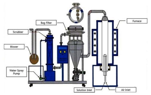
In this study, powders with the average size less than 50 nm were prepared by spraying the atomized droplets with a nozzle into the reactor that kept the raw solution at 800 °C. Changes in the characteristics of the product powder were examined depending on the variation of the inflow rate of the raw material solution. The resulting changes in the characteristics of each prepared powder depending on the variation of the reaction factors were obtained by SEM(changes in particle size distribution, average particle size and particle shape), TEM(whether the particles were single crystalline or not), XRD analysis (changes in phase and composition of the powder), and specific surface area measurement.
3. Results and Discussions
3.1. Thermodynamic study on pyrolytic reaction
When cobalt components are present in the form divalent ions in the raw material solution, the thermodynamic pyrolytic reaction expressions for forming the solid phase cobalt oxides can be represented by the following processes.9)
Equation 3) is obtained by subtracting 4 times of equation 2) from equation1).
Equation 4) subtracted by equation 5) becomes the following equation 6).
Equation 3) added by 3 times of equation 6) creates equation 7).
The thermal decomposition reaction expression 8) is obtained by adding 2 times of equation 2) and 2 times of equation 7).
Accordingly, the reaction temperatures of 700 °C, 800 °C, 900 °C and 1000 °C per equation (8) result in the standard free energy change of 37,478, 11,768, −13,007 and −36,927 J, respectively.
However, whether solid-phase Co3O4 may be formed by the pyrolytic reaction can be demonstrated not by ΔGo of equation 8-1) but by ΔG of equation 8-2).
Where, ΔG is the free energy change in any condition; ΔGo is the standard free energy change, a is the activity, and P denotes the partial pressure.
In this study, a solid phase of cobalt oxide (Co3O4) was formed at the reaction temperature of 700 °C. The fact indicates that the overall ΔG values show negative(−) values despite of the positive(+) ΔG° values in the equation 8-2), which are offset by the negative(−) but larger absolute values of RT term.
3.2. Influence of the inflow rate of the raw material solution on the properties of the formed powder
Fig. 2 shows the 5,000-fold magnified SEM image of the property change of the particles caused by the pyrolytic reaction according to the raw solution inflow rate change from 2 to 50 ml/min, at a reaction temperature of 800 °C, Co concentration in the raw solution of 100 g/L, the nozzle tip size of 2 mm, and the air pressure of 3 kg/cm2. In addition, Fig. 3 shows the 300,000-fold magnified SEM image of the changes in the characteristics of the powder formed under the same reaction conditions as in Fig. 2.
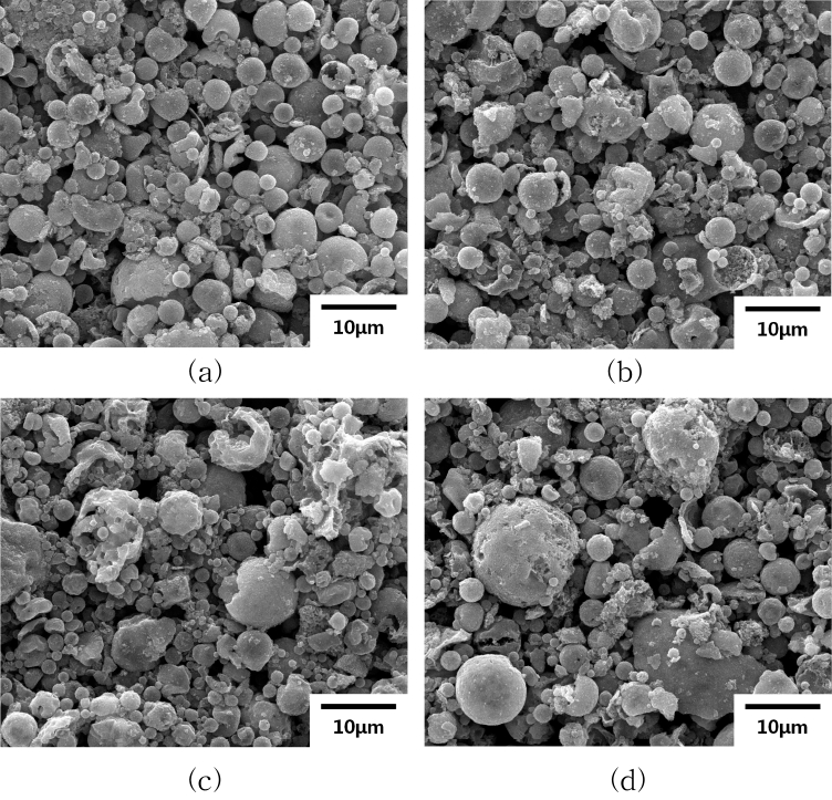
Fig. 2
SEM photographs of produced powder according to inflow speed of raw material solution at 800 °C, raw material solution of 100 g/ L cobalt, 2 mm nozzle tip size and 3 kg/cm2 air pressure. (a) 2 ml/min. (b) 10 ml/min. (c) 20 ml/min. (d) 50 ml/min.
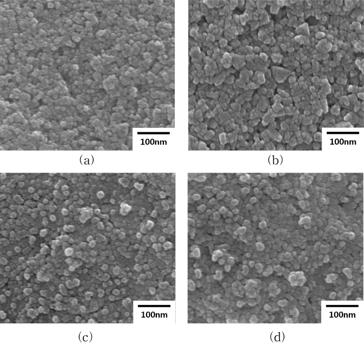
Fig. 3
SEM photographs of produced powder according to inflow speed of raw material solution at 800 °C, raw material solution of 100 g/ L cobalt, 2 mm nozzle tip size and 3 kg/cm2 air pressure. (a) 2 ml/min. (b) 10 ml/min. (c) 20 ml/min. (d) 50 ml/min.
As shown in Fig. 2, the droplets finally formed by pyrolytic reaction showed more fragmented shape and highly non-uniform particle size distribution by the increasing inflow rate. On the other hand, Fig. 3 shows that the nano-sized particles forming the droplets indicate increasing average particle size from about 25 to 40 nm as the increase in the raw solution inflow rate from 2 to 10 ml/min, while the average particle size does not change significantly as the increase in the inflow rate from 10 to 50 ml/min. Typically, the average particle size of the droplet formed by two-fluid nozzles can be expressed by the following equation 9).12)
Where, X is the average particle size, σ is the surface tension of the solution, ρ is the density, υ is the injection velocity of the solution, μ is viscosity, QL is the amount of solution, and Qa represents the intake air amount. Therefore, it is considered that the final average particle size of the powder is very small at about 25 nm and the particle size distribution appears relatively uniform because the atomized droplet size gets small and there is almost no split of droplet phenomenon in the course of thermal decomposition, at a very low inflow rate of the solution of 2 ml/min. In particular, as shown in Fig. 2(a), when the inflow rate of the solution is 2 ml/min, the droplet forms indicated relatively uniform as well as spherical compared to the case of faster inflow rates. On the other hand, however, relatively bad split of droplets has occurred despite of very slow inflow rate. In general, when the droplet size of the atomized droplets gets smaller and the number of droplets gets larger, the cohesion of the droplets gets pronounced and the speed gets faster. To be specific, in the following formula 10),12) assuming that the cause of collisions between the droplets is the Brown movement, β can be assumed to be a constant, so the likelihood of cohesion between droplets increases significantly according to the decrease in the initially atomized droplet size.
Where, No is the initial number of droplets, Nt is the number of droplets in a certain time t, τc is 2/β, and β is the aggregation rate constant. As a result, the droplet distribution before the pyrolytic reaction shows the coexistence of very small droplets due to the slow solution inflow rate and significantly particle size-increased droplets due to the severe agglomeration between droplets, so it is expected that the particle size distribution may be very uneven of the powder finally generated by thermal decomposition. Thus, Fig. 2(a) shows that, when the inflow rate was 2 ml/min, the overall droplet size was reduced according to the decrease in the inflow rate, but the droplet size increased and severe split of droplets appeared at the same time due to the agglomeration of the droplets. In addition, Fig. 3(a) indicates that the average size of the droplet-forming particles was very small at about 25 nm, and the overall particle size distribution was uniform. This fact is considered that the droplet size reducing effect by the decrease of solution inflow rate has a main influence on the average particle size. When the inflow rate of the solution increased to 10 ml/min, the size of the atomized droplets greatly increased as shown in equation 9) in comparison with the case of inflow rate, 2 ml/min. Therefore, as the pyrolysis reaction progresses within the reactor, it gets difficult for the solvent present in the droplets to smoothly pass through the solid layer of the droplet surface, resulting in the increased pressure in the droplet, bad cleavage of droplets and more uneven particle size distribution. As shown in Fig. 2(a) and (b), the droplets were larger in size and more severe in fragmentation when the inflow rate was 10 ml/min compare to 2 ml/min. In addition, as shown in Fig. 3(b), the average particle size of the finally formed powder was about 40 nm, having been increased relatively large compared with the case of the inflow rate, 2 ml/min. The result is believed to be the phenomenon occurred by the more prevailing effect of the increasing average particle size caused by the increased droplet size by virtue of the solution inflow rate increase rather than the decreasing effect of the average particle size caused by the reduced sintering by virtue of increased vaporization heat of the solvent in accordance with the increasing split of droplet and the droplet size. When the inflow rate of the solution increases to 20 ml/min, the size of the atomized droplets increases more than that of 10 ml/min, so it gets more difficult for the solvent remaining within the droplets to pass through the solid layer formed on the droplet surface over the progress of the pyrolytic reaction, which causes the pressure inside the droplet to increase even larger and the droplet to fragment even worse. As a result, as shown in Fig. 2(c), it was revealed that the droplet form was very non-uniform and mostly could not exist in spherical shape but existed in severely fractured form. On the other hand, from the result of Fig. 3(c), the droplet form in Fig. 2(c) showed the similar average particle size to that of the inflow rate 10 ml/min because the droplet was composed of nano-sized particles with the average particle size of approximately 40 nm. This phenomenon is believed to be resulted from the offset of increasing effect in the droplet size, compared with the case of inflow rate 10 ml/min, after the solvent evaporation within the atomized droplets in the early stage of the reaction and the decreasing effect in the split of droplet due to the increased duration of solvent evaporation within the droplets and increased evaporation heat of solution by the increasing effect in the severity of the droplet splits due to the increased solvent inflow rate and the effect of incapable progress of sintering for a sufficient time due to the increased evaporation heat of solution. When the inflow rate of the solution increased to 50 ml/min, the atomized droplet size increased more remarkably in comparison with the case of 20 ml/min, so pressure in the droplet further increased and the droplets were divided more severely as the pyrolysis reaction proceeded. As a result, as shown in Fig. 2(d), the droplet form was more non-uniform and mostly severely fragmented. Meanwhile, from the results of Fig. 3(d), the droplet form shown in Fig. 2(d) was found to be consisted of nano-sized particles with the average particle size similar to those of the inflow rate 10 ml/min and 20 ml/min. This phenomenon is believed to have resulted from the offset of the increasing effect in the droplet size, compared with the case of inflow rate 20 ml/min, after the solution evaporation within the atomized droplets in the early stage of the reaction and the decreasing effect in the split of droplet due to the increased duration of solution evaporation within the droplets and increased evaporation heat of solution, by the increasing effect in the severity of the droplet splits due to the increased solutiont inflow rate and the effect of incapable progress of sintering for a sufficient time due to the increased evaporation heat of solution.
Fig. 49) shows the TEM structure characteristics of the particles generated by the pyrolysis process. Fig. 4(a) and (b) illustrate the FFT(Fast Fourier Transform) pattern and diffraction pattern respectively, for each particle. Each particles showed almost the same pattern, indicating that the particles generated from these results have dense single crystal structure.
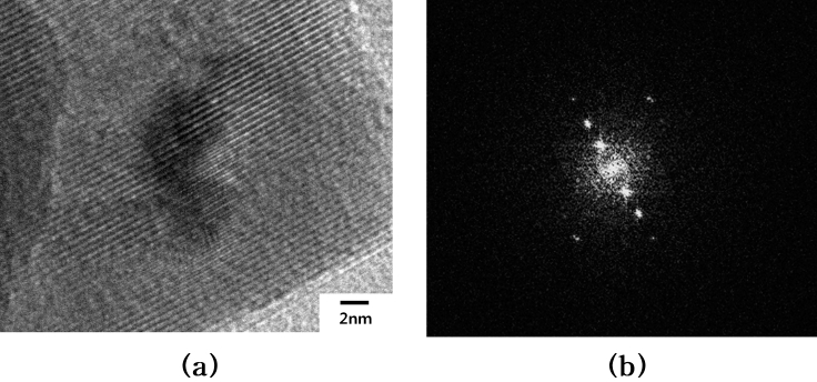
Fig. 4
TEM photographs of produced powder and selective diffraction pattern of single particle at reaction temperature of 800 °C, raw material solution of 100 g/L cobalt, 10 ml/min. inflow speed of the solution, 2 mm nozzle tip size and 3 kg/cm2 air pressure. (a) HRTEM image of an individual Co3O4 nanocrystal. (b) Selective diffraction pattern of single particle.
Fig. 5 indicates the produced phase and each peak of the powders by XRD analysis at the same reaction conditions as in Fig. 2. Even when the inflow rate was 50 ml/min, there were no unreacted products of cobalt chloride (CoCl2), which indicated that the pyrolysis reaction shown in expression 8) could proceed enough despite of the short reaction time in the inflow rate range of the present study. The XRD analysis showed that the intensities of the secondary and tertiary peaks as well as the primary peak increased significantly when the inflow rate increased from 2 to 10 ml/min. On the other hand, it turned out that the intensities of the secondary and tertiary as well as the primary peak remained constant almost without any change when the inflow rate increased from 10 to 50 ml/min. When the inflow rate was 2 ml/min, it is believed that the effect of overall droplet size decrease due to the significant decrease in the inflow rate had the dominant influence on the reduction of the average particle size to about very small 25 nm and the reduction of the XRD peak intensity as well in comparison with other reaction conditions. On the other hand, when the inflow rate increased to 10 ml/min, it is believed that the XRD peak intensity has further increased due to the increasing average particle size of the formed powder by approximately 40 nm. When the solution flow rate increased to 20 ml/min, it is believed that there was almost no change in peak intensities owing to the offset of the increasing effect of atomized droplet size due to the increased inflow rate, by the reducing effect of sintering due to the increased heat of evaporation of the solvent and the increased split of droplet due to the increased droplet size. When the solution inflow rate increase to 50 ml/min, it is believed that there was almost no change in XRD peak intensities owing to the offset of the increasing effect of droplet size after the solvent evaporation within the droplet compared with the case of the inflow rate 20 ml/min and the reducing effect of the split of droplet due to the further increased evaporation heat of solution and significantly longer duration of solution evaporation within the droplet, by the severely increasing effect of the split of droplet due to the increased solvent inflow rate and the disabling effect of full sintering reaction due to the increased evaporation heat of solution.
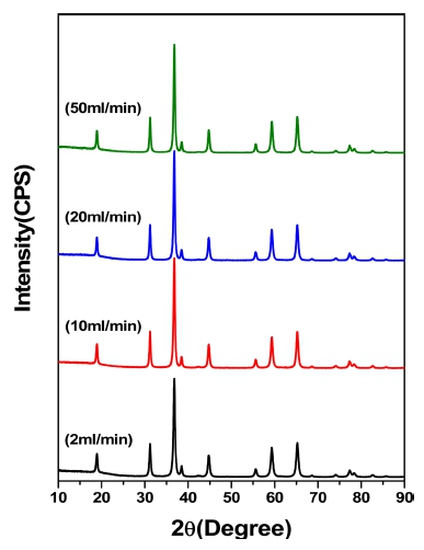
Fig. 5
XRD patterns of powder according to nflow speed of raw material solution at 800 °C, raw material solution of 100 g/L cobalt, 2 mm nozzle tip size and 3 kg/cm2 air pressure. (a) 2 ml/min. (b) 10 ml/min. (c) 20 ml/min. (d) 50 ml/min.
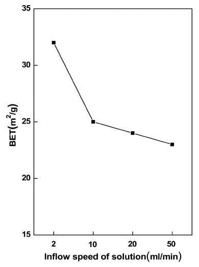
Fig. 6 shows the change of the specific surface of the resulting powder according to the change in the inflow rate under the same reaction conditions as in Fig. 2. The specific surface area was reduced by about 20 % due to the increase in the inflow rate of the solution from 2 to 10 ml/min. On the other hand, the specific surface area has remained almost constant when the inflow rate increased from 10 to 50 ml/min. When the solvent inflow rate increased from 2 to 10 ml/min, it is believed that the specific surface area has decreased relatively significantly due to the increased average particle size of the formed powders from about 25 to 40 nm, by the prevailing working of the reducing effect of the split of droplet owing to the increased atomized droplet size as well as the increased solvent vaporization heat due to the increased droplet size rather than the reducing effect of the sintering due to the increased evaporization heat of solution and the increasing effect of the split of droplet by the increased droplet size. On the other hand, when solution inflow rate increased to 20 ml/min, the specific surface area of the particles is believed to have remained nearly unchanged due to the offset of the reducing effect of the split of droplet from the increased atomized droplet size and the resulting evaporization heat of solution increase, by the increasing effect of the split of droplet due to the increased droplet size and the reducing effect of sintering by the increased evaporation heat of solution. When the solution inflow rate increase to 50 ml/min, it is believed that there was almost no change in the specific surface area of the particles owing to the offset of the significantly increasing effect of droplet size after the solvent evaporation within the droplet compared to the case of the inflow rate 20 ml/min and the reducing effect of the split of droplet due to the further increased solvent evaporation heat and significantly longer duration of solvent evaporation within the droplet, by the severely increasing effect of the split of droplet due to the increased inflow rate and reducing effect of compaction of the formed particles due to the disabled effect of full sintering reaction by the increased evaporization heat of solution.
4. Conclusion
The purpose of the present study was to identify the change in the characteristics of the particles according to the change in the inflow rate of the raw material solution through the production of cobalt oxide (Co3O4) powder of average particle size 50 nm or less by spray pyrolysis reaction using the raw cobalt chloride solution and selfmade spray pyrolysis apparatus.
When the inflow rate of the raw solution was 2 ml/ min, the droplet forms indicated relatively uniform and spherical compared to the cases of faster inflow rates. On the other hand, as the inflow rate of the raw solution increased, the droplet formed by the pyrolytic reaction showed more divided form and the particle size distribution was more uneven as well. The average particle size of the produced powder was about 25 nm. In the case the inflow rate increased to 10 ml/min, the average particle size has increased to 40 nm. While the inflow rate increased from 20 to 50 ml/min, the average particle size was found not to change notably.
The XRD analysis showed that the strength of the XRD peaks has remarkably increased when the inflow rate of the solution increased from 2 to 10 ml/min. On the other hand, the peak intensity kept almost constant without change when the inflow rate increased from 10 to 50 ml/ min. With the increase in the inflow rate of the solution from 2 to 10 ml/min, the specific surface area of the particles remarkably decreased by approximately 20 %. On the other hand, the peak intensity kept almost constant without change when the inflow rate increased from 10 to 50 ml/min.
