

1. Introduction
2. Experimental Procedure
3. Results and Discussion
3.1. Structural characterizations
3.2. Electrochemical analysis
5. Conclusion and Prospects
1. Introduction
Owing to the high energy density of roughly 282 kJ mol-1, clean combustion product (H2O), and an efficient electrical energy transformation via fuel cells, hydrogen is regarded as one of the most perfect replacements for the conventional energy resources.1,2) Water splitting by electrocatalysis is an emerging technique to produce hydrogen.3) Two half-reactions are involved in the synthesis of hydrogen from water electrolysis: the anodic four-electron oxygen evolution reaction (OER) and the cathodic two-electron hydrogen evolution reaction (HER). The OER involves four proton-coupled electron transfer (PCET) steps, producing OH*, O*, and OOH* intermediates. It requires a high overpotential to drive, resulting in sluggish dynamics which reduce overall hydrogen production efficiency. Therefore, OER is the bottleneck in electrocatalytic water splitting,4,5) and this fact underlines the pressing need to develop better electrocatalysts for OER. Currently, noble metal catalysts, such as Ir- or Ru-based nanostructured oxides, are commonly used due to their high OER catalytic activity but they suffer from scarcity, high cost, and quick deactivation during operation, which highlights the need of cost-effective alternatives, and which are abundant in Earth’s crust. So far, several materials have been as explored as electrocatalysts for OER such as, transition metal sulfides (TMS),6,7) oxides,8) nitrides,9) borides,10) phosphides5) and hydroxides or double hydroxides;11,12) these have been investigated as potential alternatives to traditional precious metal-based OER catalysts. Among them, TMS are highly regarded as effective catalysts for OER due to their unique electrical characteristics such as higher electrical conductivity than metal oxides due to their narrow band gap,13) easily modifiable electronic structure and composition.6,7) Doping TMS with heteroatoms is a powerful technique to create highly efficient water-splitting electrocatalysts for HER and OER. Heteroatoms can optimize adsorption energies of reactive species in water splitting reactions by regulating electronic structure, increasing catalytic active sites, and creating defects and distortions in the lattice.13,14) Fe is the most abundant transition metal element in the earth’s crust at a very low cost.15,16) According to some groups, adding Fe elements to nickel sulfides is an effective way to improve OER performance because it allows the electronic structure to be tuned to modify the active sites and the adsorption of the intermediates.17,18) Motivated by these findings, in this work we have prepared Fe (0.1 %)-doped NiS2 nanoparticles by simple one step hydrothermal reaction. In this study, the synthesis of Fe-doped NiS2 employs a cost-effective and environmentally friendly approach through a simple one-step hydrothermal method. This process utilizes earth-abundant materials like nickel and iron, avoiding the need for precious metals and complex multi-step procedures. The hydrothermal method’s simplicity and efficiency make it highly suitable for potential large-scale production, reducing manufacturing costs and environmental impact. The surface electronic structure is regulated, resulting in lower activation energy and increased OER activity. The 0.1 % Fe-doped NiS2 (called Fe-NiS2) shows an overpotential of 180 mV at 10 mA cm-2 and reduced Tafel slope of 150 mV dec-1 and high working stability for 40 h. The doped material has shown enhanced catalytic activities as demonstrated by various methods such as linear sweep voltammetry (LSV), and electrochemical impedance spectroscopy (EIS) measurements.
2. Experimental Procedure
To synthesize NiS2 nanoparticles, a simple one step hydrothermal reaction was performed. Shortly, 2.85 g of nickel chloride hexahydrate (NiCl2 ‧ 6H2O), 1.44 g of sodium hydrosulfide (NaHS) and 2.88 g of urea (NH2CONH2) were dissolved in 80 mL of distilled water. The solution was kept under magnetic stirrer overnight. Then, the solution was transferred to stainless steel autoclave and kept at temperature of 140 °C for 10 h. The autoclave was allowed to cool down naturally and the resulting solution was washed repeatedly with alternate cycles of ethanol and water. The product dried at 80 °C for 12 h to get NiS2 powder. The powder was annealed at temperature of 400 °C for 4 h. Similar procedure was carried out for the preparation of Fe-NiS2, with addition of 29 mg of ferrous chloride tetrahydrate (FeCl2 ‧ 4H2O) as Fe precursor.
The working electrodes of NiS2 and Fe-NiS2 were prepared by depositing slurry of a mixture of obtained sample powder, carbon black and polyvinylidene difluoride (PVDF) in 80 : 10 : 10 ratio on carbon cloth substrate. The prepared electrodes were dried for 12 h at 120 °C under vacuum. The LSV was taken at a scan rate of 1 mV s-1. The EIS technique was conducted at an amplitude of 10 mV alternating voltage within a frequency range of 100 kHz~100 mHz.
3. Results and Discussion
3.1. Structural characterizations
The XRD (X-ray diffraction) pattern for NiS2 and Fe-NiS2 is shown in Fig. 1. which demonstrates good crystalline nature and absence of any impurity in both samples. All diffraction peaks correspond to cubic Vaesite, NiS2, and are consistent with previously reported data (JCPDS Card File No. 01-089-7142). The major peaks at 31.5°, 35.4°, 38.8°, 45.2°, and 53.5° correspond to (200), (210), (211), (220) and (311) lattice planes of NiS2. The crystallite size has been calculated using modified Scherrer equation,19) which can be written as,
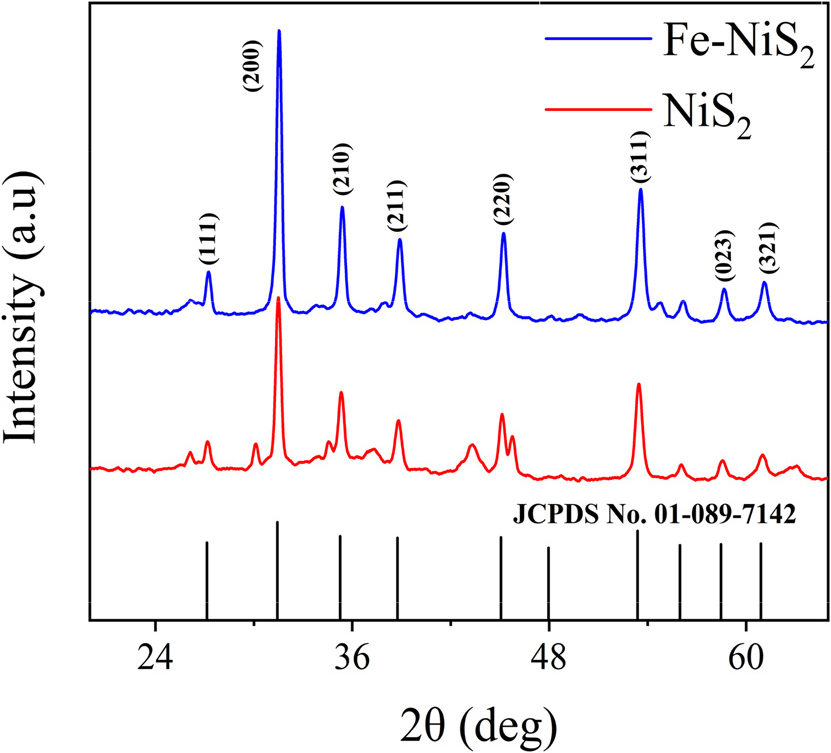
where, K is the dimensionless shape factor, (typically around 0.9), β is full width at half maximum measured in radians, λ is X-ray wavelength in nanometers, L is crystalline size, θ is Bragg angle (in radians). If we plot lnβ against ln(1/cosθ), then a straight line with a slope of around one and an intercept of about lnK/L must be obtained, and from that intercept and using λ (λCukα1 = 0.15405 nm) calculated crystalline size was 26.68 nm for NiS2 and 26.42 nm for Fe-NiS2, and it indicates that Fe doping maintains the nanostructure of NiS2. No other extra peaks observed in Fe-NiS2 which indicates absence of impurity and extra phase in material and successful doping of Fe into NiS2. To understand the morphology of the prepared sample, scanning electron microscopy (SEM) has been performed [Fig. 2(a)]. SEM images show the morphology having agglomerated nanocubes which are distributed non-uniformly. SEM analysis reveals that Fe-doped NiS2 exhibits some degree of agglomeration, but the agglomerates appear more uniform and less prone to further aggregation. The average size of one such nanocube found to be 0.12 µm. The energy dispersive X-ray spectroscopy (EDS) elemental mapping depicts the uniform distribution of Fe element in NiS2.
To further study the microstructure of the Fe-NiS2, transmission electron microscopy (TEM) was performed. The cuboidal structure of Fe-NiS2 was confirmed by low power TEM image [Fig. 2(b, d)]. From high resolution TEM images [Fig. 2(c)], one can see clearly separated lattice fringes showing polycrystalline nature of sample. TEM analysis reveals well-defined crystalline regions in Fe-doped NiS2, with fewer defects and reduced lattice strain. The EDS elemental mapping from TEM shows that the elements Ni, S and Fe are evenly distributed in the sample and the atomic doping percentage of Fe was 0.1 %. The TEM, SEM and XRD altogether support the successful synthesis of 0.1 % Fe-doped NiS2.
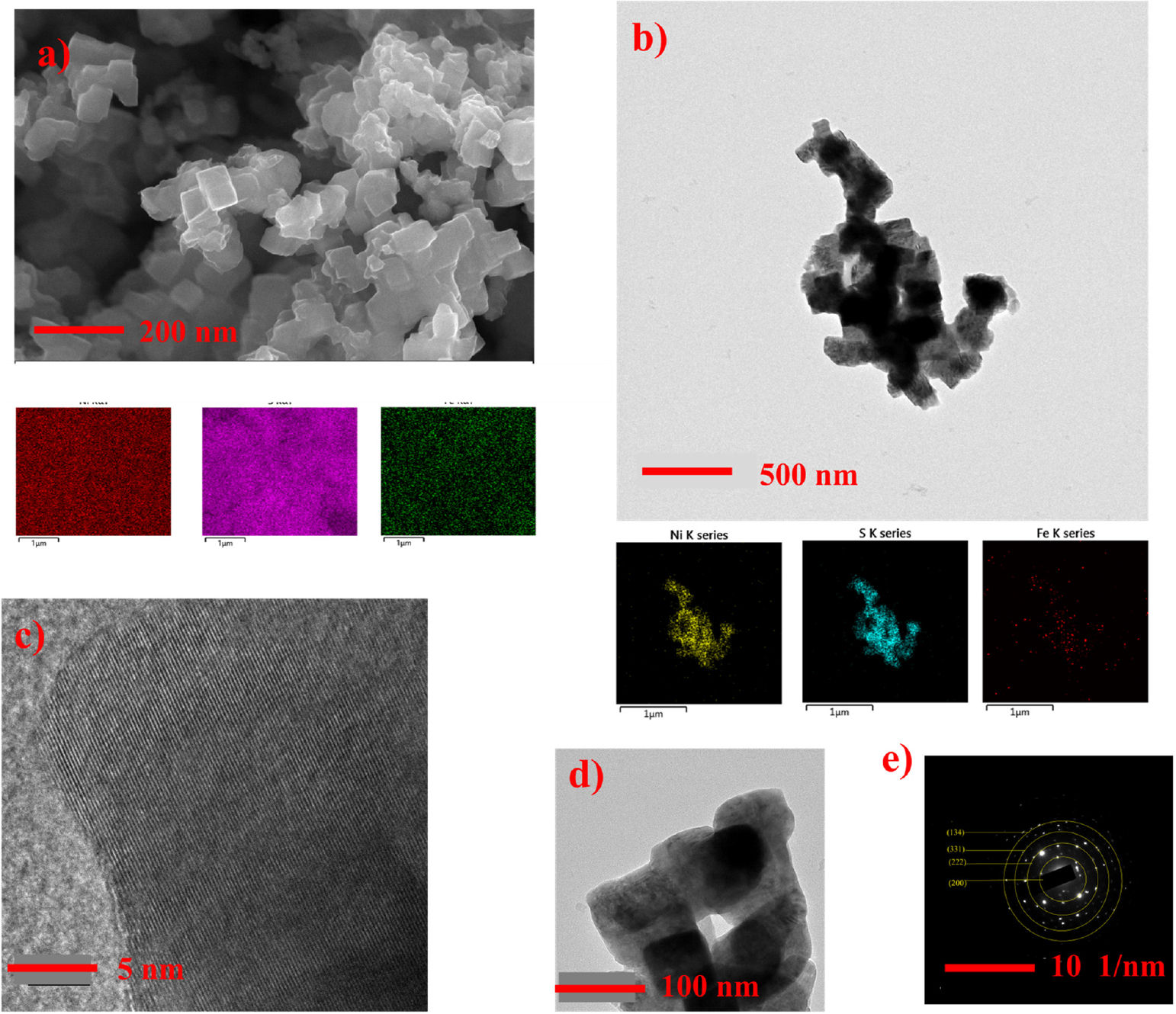
Fig. 2.
Structural analysis of Fe-NiS2 (a) SEM image for Fe-NiS2 and corresponding EDS (energy dispersive X-ray spectroscopy) elemental mapping (b) TEM image and EDS mapping for Fe-NiS2 (c) High resolution TEM image at 5 nm (d) low power TEM image at 100 nm (e) SAED (selected area electron diffraction) pattern.
3.2. Electrochemical analysis
The electrocatalytic activity of prepared electrodes was assessed using a conventional three electrode system. The platinum wire acted as a counter electrode and saturated calomel electrode as a reference electrode while NiS2 and Fe-NiS2 acted as a working electrode. 1 M KOH was used as an electrolyte. The standard electrode potential for OER is 1.23 V vs. RHE (reversible hydrogen electrode). However, hysteresis kinetics, activation barrier, and series resistance require an extra voltage distant from equilibrium at the anode to drive the OER process.5) Overpotential (η) refers to the difference between true and equilibrium potential. The overpotential of OER can be calculated as,
At a current density of 10 mA cm-2 the overpotential for NiS2 was 250 mV while that of Fe-doped NiS2 (Fe-NiS2), it was reduced to 180 mV showing enhanced OER activity owing to Fe doping as depicted in polarization curves [Fig. 3(a)]. This significant reduction in overpotential underscores the improved catalytic performance of Fe-doped NiS2. To investigate the kinetics of the OER process, Tafel slopes of the two samples are estimated from polarization curves [Fig. 3(c)]. The Tafel plots of electrocatalyst are obtained using the Tafel equation,
where, η, j, and b are the overpotential, current density, and Tafel slope, respectively while ‘a’ is a constant. The Tafel slope for NiS2 was 167 mV dec-1 while that of Fe-NiS2 was 150 mV dec-1. This reduction indicates an improved rate of electrochemical reactions upon Fe doping, demonstrating enhanced catalytic efficiency. The EIS technique can be used to analyze charge transfer properties and conductivities of electrode materials. The charge transfer resistance (Rct) in the high frequency range can be related to the rate of charge transfer between the material and the electrode/electrolyte contact. A lower Rct leads to increased catalytic activity and faster reactions.2,20) The charge transfer resistance value measured for Fe-NiS2 was 120 Ω which is lower than that of NiS2 (500 Ω) as shown in Fig. 3(b). This reduction in Rct suggests that Fe doping facilitates more efficient charge transfer, contributing to faster reaction kinetics. This fact underlines that Fe-NiS2 nanocubes had higher conductivity and faster electrode dynamics, which is consistent with the lower Tafel slope and overpotential measurements. Fe doping resulted in enhanced conductivity and reaction kinetics. Electrochemical specific surface area (ECSA) is a crucial metric for electrocatalytic reactions. The current obtained from electrode potential scanning is proportional to the surface area exposed in electrolyte solution.21) Double-layer capacitance (Cdl) measures the size of an electrochemical surface area. We measured the cyclic voltammetry (CV) curves at various scan rates in the non-Faradaic region [Fig. 3(d, e)]. By plotting redox current density difference against scan rate, the slope gives Cdl value. From Fig. 3(f), Fe-NiS2 had a higher electrochemical double-layer capacitance of 59 mF cm-2 as compared to NiS2 (46 mF cm-2). Larger electric double-layer capacitance indicates more catalytic active sites. The results show that the number of active sites in unit area of product can be increased by Fe doping. Doping NiS2 by Fe increased the number of active sites.
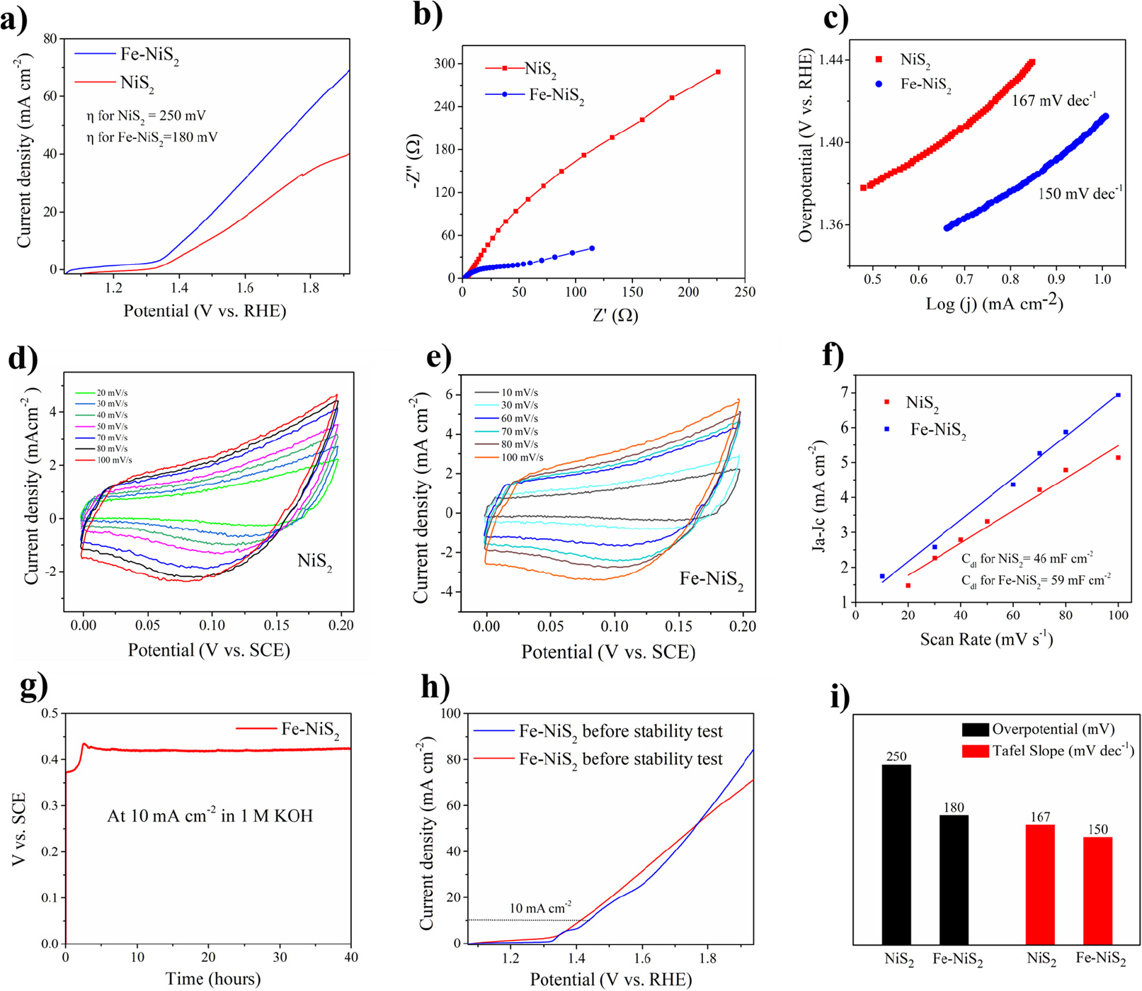
Fig. 3.
Electrochemical performances of electrocatalysts (a) Polarization curves for NiS2 and Fe-NiS2 at scan rate of 1 mV s-1 (b) Nyquist plot of electrochemical impedance spectra of electrodes (c) Corresponding Tafel plots (d, e) Cyclic voltammetry curves in non-faradaic region (f) Anodic and cathodic current different against scan rate (g) Chronoamperometry test at 10 mA cm-2 (h) Polarization curves for Fe-NiS2 before and after stability test (i) Bar diagram showing overpotentials for NiS2 and Fe-NiS2.
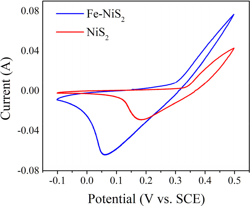
As shown in the CV plot (Fig. 4), a significant shift in the redox peaks of Fe-doped NiS2 was observed in comparison to undoped NiS2, demonstrating that Fe insertion notably modifies the electronic structure of NiS2 and improves the electrocatalytic activity of NiS2 for OER. Such a shift indicates that Fe-doping modulates the adsorption energetic of important intermediates (OH*, O*, and OOH*) involved in OER and thus allows for the preferential formation and conversion of these intermediates. Indeed, the larger current density of the Fe-doped NiS2 indicates an enhanced catalytic activity. The improvement can be ascribed to denser active sites and enhanced charge transfer dynamics with Fe doping. It has been reported that Fe doping in NiS2 stabilizes the metallic phase, which is favorable for OER activity.22) Moreover, the larger peak separation of the anodic and cathodic processes in the CV indicates a faster charge transfer kinetics associated with Fe-NiS2. The modification in the electronic structure and stabilization of high-energy intermediates for Fe-doped NiS2 is consistent with previous reports that show significantly enhanced OER activities in Fe-doped materials.23) Ultimately, the shift of redox peaks in Fe-doped NiS2 is due to electronic structure changes caused by Fe doping, which boost intermediate adsorption, alleviate transition-state stabilization, and facilitate charge transfer dynamics. The combination of the effects accounts for the enhanced OER performance of the Fe-doped NiS2 catalyst, which agrees well with previous reports.
To check the robustness and stability of Fe-NiS2, chronoamperometry test has been conducted at a current density of 10 mA cm-2. It shows the overpotential remains intact even after continuous operation of 40 h. The electrochemical stability of Fe-doped NiS2 is highlighted by its superior cycling performance. The LSV taken after stability test deviates slightly from the initial LSV curve with an overpotential of 200 mV at 10 mA cm-2. It indicates the high stability of Fe-NiS2 and durability of Fe-NiS2. According to the literature, Fe doping enhances electronic conductivity by increasing the density of states at the top of the valence band. Here, from our results the doping of NiS2 by 0.1 % has significantly improved the electrocatalytic performance for OER and this is consistent with the previous report.24) This improvement stems from the modified electronic structure due to Fe doping, facilitating easier electron flow during electrochemical reactions. Fe doping contributed to a more stable material structure and enhanced catalytic properties, as supported by SEM, TEM, and electrochemical analyses. We have given contribution for enhanced performance solely to doping by Fe, but we cannot neglect the fact that the TMS undergo auto-oxidation in OER under alkaline conditions and gets converted into their oxides or oxyhydroxides, which may have a part on enhancing OER mechanism, but this study doesn’t cover that aspect.13) To compare the electrocatalytic activity of the synthesized Fe-NiS2 with other reported electrocatalysts for OER performances, we have added Table 1.
Table 1.
Comparison of OER performances for synthesized Fe-NiS2 with other reported electrocatalysts.
| Electrocatalyst |
Overpotential (mV) |
Current density (mA cm-2) | Reference |
| Fe-NiS2 | 180 | 10 | This work |
| Fe0.1Ni0.9S2 | 260 | 10 | (22) |
| Fe-NiS/NiS2 | 361 | 100 | (25) |
| Fe-doped NiS-NiS2 | 270 | 50 | (26) |
| Fe-doped NiS2 | 277 | 10 | (24) |
| Fe-doped NiS2 on NiFe-CNFs | 287 | 30 | (27) |
| (Co,Fe-NiS2) | 242 | 500 | (28) |
| W-NiO/NiS2 | 263 | 10 | (29) |
| Se-doped NiS2 | 343 | 50 | (30) |
| P-doped NiS2 on Ni foam | 255 | 20 | (31) |
| CoOx/FeOx/CNT | 308 | 10 | (32) |
| Ni59Cu19P9 | 307 | 10 | (33) |
| NiS2/NiSe2 | 290 | 20 | (34) |
| NiS/Fe3O4 HNPs@CNT | 243 | 10 | (35) |
| Hollow Fe-CoxP | 300 | 10 | (36) |
5. Conclusion and Prospects
In this work, we have synthesized 0.1 % Fe-doped NiS2 by simple one step hydrothermal method. This synthesis route aligns well with green chemistry principles, minimizing waste and energy consumption. The resulting Fe-doped NiS2 demonstrates remarkable improvements in electrocatalytic performance for OER, with enhanced activity and stability compared to undoped NiS2. The reduced overpotential and Tafel slope highlight the efficacy of Fe doping in enhancing the catalytic properties of NiS2. The improved conductivity and reaction kinetics are likely due to the tuning of electronic structure of NiS2 owing to 0.1 % doping by Fe element, which enhances the material’s stability and durability under operational conditions. To further develop this catalyst for real-world applications in energy conversion technologies, several strategies could be pursued: fine-tuning the Fe doping concentration to optimize the balance between catalytic activity and long-term stability, exploring the integration of the catalyst into practical devices like electrolyzers and fuel cells, investigating its performance in other energy conversion reactions such as hydrogen evolution or overall water splitting, and conducting extensive durability tests under industrial conditions. This work underscores the potential of Fe-doped NiS2 as an efficient and robust catalyst for electrochemical applications, paving the way for further exploration and optimization of transition metal-doped sulfides in energy technologies. Our study could play a crucial role in developing high-performance, cost-effective catalysts for large-scale renewable energy applications, bringing us closer to sustainable hydrogen production and energy storage solutions.
