

1. Introduction
A bond coat is a critical part of the thermal barrier coatings (TBCs). Not only is the oxidation resistance important but also effective ID barrier effect of paramount importance. It has been found elsewhere, almost unanimously that ID elemental migrations either from the substrate to coatings or vice versa are the major longterm performance obstacles.1-7) That is because the ID depletes the oxide formers or enriches the oxide detrimental elements into BC. Thus, base alloy (e.g., superalloy) mechanical integrity is at risk due to the massive elemental ID. A large number of publications is dedicated to make the BC diffusion barrier,7-10) but little success is recorded. However, the use of minimal quantities of reactive elements (REs), such as Zr, Hf, and Y was proved to beneficial for oxidation resistance.11-18) This is the main feature of the present work and very little work is done on comparative analysis of ID behavior of REs/and Pt doped coatings to the best of our knowledge. Therefore, this study is dedicated to understanding the ID caused by oxidation and vacuum treatments and trends of Pt, Zr, and Al migrations.
2. Materials and Methods
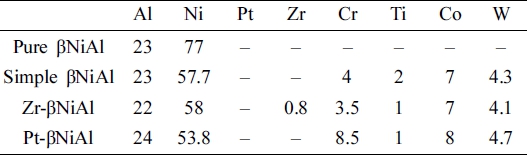
The aluminide coatings were deposited on CMSX-4 superalloy having a nominal composition of 61.42 Ni, 6.40 W, 2.90 Re, 5.64 Al, 1.03 Ti, 6.60 Ta, 9.60 Co, 6.40 Cr and 0.10 Hf wt%, and also on pure nickel (99.99 %). Both substrates were cut into 5 × 5 × 2 mm discs, progressively ground by 1200 grit SiC papers, and ultrasonically cleaned in an ethanol. This was followed by the deposition of coatings i.e. aluminizing and zirconizing using the pack cementation technique. Three sets of coatings were prepared, while the fourth set of Pt-βNiAl single-phase BC was provided by Rolls Royce during my PhD studies. Thanks to Prof. Ping Xiao for his support for provision of samples and facilities. The bond coat samples referred in this work to simple βNiAl has been deposited onto Ni-based alloy, whereas pure βNiAl samples have been deposited onto pure Ni substrates. Such samples were cut into required discs from the same coated sheet (for identical comparison) and received thermal treatments in a vacuum (processing) and the air (oxidation) at 1,150 °C for 100 h. More importantly, oxidation treatment was followed by fast cooling, at the cooling rate > 150 °C/min, i.e. coating samples taken out of furnace from 1,150 °C to room temperature. The averaged surface chemistries obtained using energy dispersive xray fluorescence spectroscopy (EDXRF) is shown in Table 1. For further microstructural and compositional analyses, the scanning electron microscope (SEM) coupled with energy dispersive spectroscopy (EDS) was used in the present study.
3. Results
3.1. Coatings Cross-sections
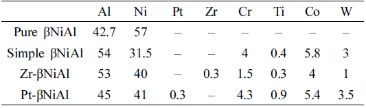
Fig. 1 show the Zr-βNiAl coatings that were processed in two steps, at the first stage, Zr was introduced into γ- Ni/γ’-Ni3Al structure of CMSX-4 superalloy as seen in Fig. 1(a). This was beneficial since it blocked the substrate elements from migrating into the coating, and due to the high processing temperature, it dissolved more Zr than that of predicted solubility limit. This was followed by second aluminizing step wherein Zr-γ/γ’ converted into βNiAl rich with Zr content. The excess of Zr is seen to be precipitated out into entire βNiAl layer, specifically at the BC-alloy interface.
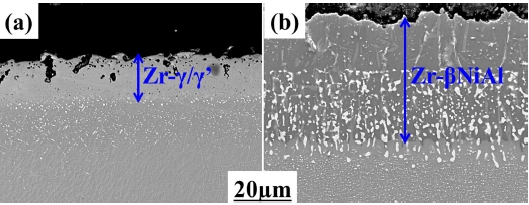
Fig. 1
The processing sequence of the coatings formed, showing the diffusion barrier effects. (a) In the first step, Zr-enriched-γ/γ’ is formed that is followed by aluminizing as seen in (b).
Similarly, Fig. 2(a-b) shows the Platinum modified bond coats. Platinum was introduced into γ/γ’ matrix of superalloy and subsequent aluminizing caused conversion to βNiAl structure. Similar to Zr, in the first step, Pt blocks out-diffusing elements (electroplating-diffusion) due to its higher solubility in the substrate than Zr. Thus, the second aluminizing step converts Pt-γ/γ’ into Pt- βNiAl structure with the least substrate elements.
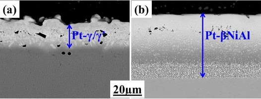
Fig. 2
Similarly (as in Fig. 5), (a) at first Pt-γ/γ’ is formed which is followed by aluminizing as seen in (b). So, the first step seals off the substrate (blocks substrate elements) leaving behind impurities and the second step develops clean aluminide coatings.
Fig. 3 shows the microstructures of as-deposited, vacuum treated, and oxidized coatings, respectively. The as-deposited BCs are typically two-layered structure consisting of an outer βNiAl and inner precipitates (ppts) rich interdiffusion zone (IDZ). Fig. 3(a-i – iii) presents pure βNiAl in as-deposited, vacuum treated and oxidized conditions, respectively. Under vacuum, it has undergone high ID (promoting γ’-Ni3Al formation), while after oxidation left it completely transformed into γ’-Ni3Al. Similarly, Fig. 3(b-i – iii) corresponds to simple βNiAl, which also followed an identical trend as in pure βNiAl. However, comparably minimum βNiAl to γ’-Ni3Al transformation was noticed. On the contrary, Zr-βNiAl shown in Fig. 3(c-i) – iii remained stable during vacuum treatment but experienced some βNiAl to γ’-Ni3Al transformation under oxidation. While Pt-βNiAl shown in Fig. 3(d-i – iii), showed a 10 ~ 15 % reduction in BC thickness, interface waviness and fading up of its initially white contrasted outer βNiAl layer under vacuum. This is due to Pt inward departure (towards the substrate) from initially ~ 10 to 2 at% [seen in Fig. 3(d-ii-inset)]. Whereas, it remained fairly stable under oxidation treatment except for some localized transformation into γ’-Ni3Al.
3.2. The chemical composition of BCs
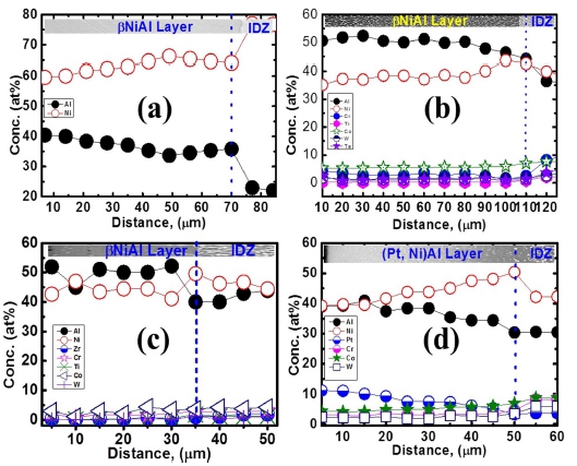
All BCs shown in Fig. 4(a-d) have a more or less similar amount of Al, except for simple βNiAl, which contains high Al content [Fig. 4(b)], and thereby confirming typical βNiAl composition. Other elements are also shown therein, notably Pt and Zr contents.
3.3. Oxide Morphologies
Fig. 5(a) represents the spallation map of the pure βNiAl, which shows the lowest spallation resistance. Moreover, large voids, groves, and channels are visible at the breakage sites, and also its magnified inset shows oxide porosity. Similarly, Fig. 5(b) presents simple βNiAl that exhibits high spallation and at some locations Ti/Cr/ Ta rich ppts could be noticed. The dense and clean oxides of both Zr and Pt modified BCs are visible in Fig. 5(c-d), respectively.
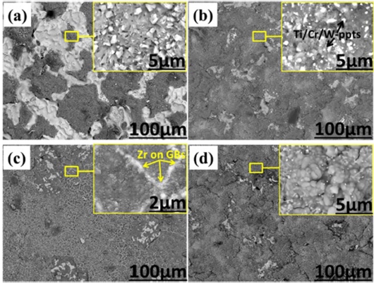
Their corresponding spallation lives are slightly comparable to each other, but an excellent match can be seen when compared to pure βNiAl and simple βNiAl [Fig. 5(a-b)]. More interestingly, Zr-rich-particles could be found segregated at oxide grain boundaries, thereby a kind of ridge-sealing effect that could be seen in Fig. 5(cinset). Fig. 5(d-inset), on the other hand, presents clean oxide formed on Pt-βNiAl.
Table 2 illustrates the chemical composition of the spalled localities (failure sites), which reveals βNiAl - γ’- Ni3Al transformation. It should be noted here that this γ’- Ni3Al is quite different in composition to standard γ’- Ni3Al of an alloy. It is richer in refractory elements including Ti.
3.4. Mass Gain Trends and EDS Mapping
EDS mapping of the oxide top surface, cross-section, and its broken grains were analyzed to understand the presence of Zr therein, as shown in Fig. 6(a-c), respectively.
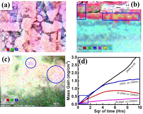
Fig. 6
(a-c). Represents the EDS maps of the top surface, crosssection, and the broken oxide layer/grains of Zr-βNiAl respectively, and TG plots of all coatings are shown in (d).
The examination of these maps indicates the presence of Zr on top or at the location of circles and rectangles [Fig. 6(a-c)]. The isothermal oxidation kinetics of different coatings at 1,150 °C for 100 h in laboratory air is presented in Fig. 6(d). The square boxed bottom of the curve shows an accelerated transient oxidation stage in Zr-βNiAl and thereafter it attained a steady-state condition. So, the reduction of mass gain is visible within the plot. Furthermore, the plot of Zr-βNiAl implies that mass gain is fast at the initial oxidation stage while thereafter coating attains steady-state by forming α-Al2O3. Pure and simple βNiAl gained the highest masses, whereas the lowest mass gain was noticed in Pt-βNiAl. Therefore, the order of mass gain is as follows: pure βNiAl > simple βNiAl > Zr-βNiAl > Pt-βNiAl. So, all coatings followed an identical trend, i.e. progressive growth except Zr- βNiAl, which showed high mass gain at the initial stage thereafter attained a steady state.
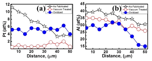
Fig. 7(a-b) shows the concentration profile of platinum and aluminum in Pt-βNiAl coatings under different conditions. Extensive platinum migration into substrate is witnessed during vacuum treatment [Fig. 7(a)]. Similarly, less aluminum is seen than that of as-deposited coating. This suggests the Al in-diffusion or inward diffusion too. More interestingly, during oxidation, Pt amount remained in the layer, which is more than twice than that of vacuum treated sample. In brief, Al and Pt are reduced due to prolonged vacuum treatment when compared to as-deposited condition. However, during oxidation of asdeposited BC, platinum was also reduced but much lesser than that of vacuum counterpart. While aluminum also showed reduction which is natural process i.e. formation of oxide.
4. Discussion
The present discussion is divided into three sub-sections. First, it covers pure and simple βNiAl, second it focuses on the Zr and third Pt effects on BC performance are discussed.
4.1. Pure and simple βNiAl
Ideally, vacuum treatment is meant to stop the destabilization by oxidation and allows examination of the coating-substrate interactions, in terms of ID. Nevertheless, another driving force is that the substrate and coatings are not in thermodynamic equilibrium.
The thickness rise in both simple and pure βNiAl during vacuum treatment indicates considerable coatingsubstrate ID [Fig. 3(a)-ii and (b)-ii]. Upon oxidation, pure βNiAl retained its thickness more or less the same, however, transformed entirely into γ’-Ni3Al [see Fig. 3(a)]. This is because of the strong compositional gradient between pure Ni and βNiAl phases. Whereas, simple βNiAl coating showed ever-increasing trend in thickness. Its interdiffusion zone increased more than twice to initial one. Also, it has undergone some phase transformation from βNiAl to γ’- Ni3Al that could be seen as a white contrasted network in Fig. 3(b)-iii. However, phase transformation is not that severe as in pure βNiAl because Ni activity in the former is high compared to the later one.
In general, simple βNiAl witnessed better performance than that of pure βNiAl. However, from substrate elemental migration [Fig. 5(b) and (b-inset)] towards the oxide scale and gained second highest mass during oxidation [Fig. 6(d)]. The oxide grown on simple βNiAl is rich in Ti, W, Ni, and Cr ppts, on the other hand, pure βNiAl oxide is porous and rough. Therefore, it strongly implies that either pure βNiAl or simple βNiAl needs to be stabilized to avoid diffusion imbalance and out-diffusion, respectively.
4.2. Zr-βNiAl
It is important to understand the underlying mechanisms behind the improved performance of βNiAl when doped with a small concentration of Zr. The as-deposited Zr- βNiAl coating exhibited the diffusion barrier effect to a reasonable extent, at both initial (during processing, Fig. 1) and final (oxidation) stages in terms of its thermal stability.
Because the Zr-βNiAl was processed in two steps [see Fig. 1] thereby offering two main advantages; i) it blocks the substrate elements from migrating into the coating, and ii) due to the high processing temperature, it dissolves more Zr than that of predicted solubility limit. The excess Zr in the coating is precipitated out specifically at the BC-alloy interface. This is beneficial due to two reasons: (1) creating Zr reservoir necessary for long term oxidation and (2) the presence of such ppts at BC-alloy interface inhibits the out-diffusing elements, hence reducing flux to BC, making it cleaner. Thus, the potentially diffusion barrier effect starts at the BC-alloy interface. As a result, clean BC forms pure oxide [Fig. 5(c-inset)] due to the continuous migration of Zr to oxide scale grain boundaries (GBs). When Zr-βNiAl was treated in a vacuum, it has retained thickness, which means that the intake of the substrate’s elements is the smallest [in Fig. 3(c)]. Moreover, upon oxidation, the Zr migrates from βNiAl GBs19) to the BC-oxide interface to scale GBs.20) Such migration translates significant benefits, for instance reducing the scale growth by changing the oxidation mechanism,20) i.e. it demotes cationic migration and promotes anionic flux. This makes BC thermally stable because of the low consumption of Al. Because of the preferential blockage of GBs by Zr ions (bigger in sizes) restricting most of the substrate’s elemental out-flux making oxide free from segregants [Fig. 5(c-inset)]. Thus, sealing of the scale GB [Fig. 5(c-inset)], which is rarely found in literature. This strongly (experimentally) supports the segregation model which is well established. Therefore, the oxide is pure. More, the examination of Zr-rich ppts into βNiAl showed some Cr and Co, which is beneficial to stabilize its structure.21)
Moving now to a common controversial aspect of the Zr influence, that is, whether it modifies oxidation stages or not. According to the dynamic segregation model,20) REs begin to affect once the transient oxidation stage is over, while some researchers believe it only affects the transient stage.16,22) To address such controversy, after the isothermal oxidation test [Fig. 4(d)], the oxide elemental mapping was done to confirm the presence of the Zr. That is indicative of its effects. The elemental mapping [Fig. 4(a)] shows the presence of Zr on the oxide surface. The other map of the oxide-coating interface and third broken site of grains was acquired that all confirm the presence of Zr within them [Fig. 4(b-c)]. The Zr inside the broken grains shows that it oxidized at the initial stage and promoted α-Al2O3 thereafter. This suggests interface binding by oxide pegging. The examination of thermo-gravimetric (TG) plots shows the fast mass gain [rectangle part of Fig. 6(d)] at the transient stage, and finally, it attains a steady-state condition at latter stage. Therefore, it emerges from the present set of experimental conditions that Zr-promotes alumina nucleation at the initial stage and maintains steady-state thereafter. Such behavior by Zr addition is quite distinctly visible from other TG plots [Fig. 6(d)]. Therefore, the authors propose that Zr not only modifies the steady stage of oxidation but the transient state too. Because at the initial stage, Zr present on coating surface oxidizes faster and provides nucleation sites for α-Al2O3 to grow as discussed earlier. Even during the heating cycle of oxidation due to its reactive nature and at steady state preferential anionic flux could be promoted.
4.3. Pt-βNiAl
Initially, it was believed that Pt could minimize Al indiffusion 23) and substrate out-diffusion.24,25) However, it is not the case during oxidation. Also, the βNiAl structure is susceptible to both, in and out-diffusion during thermal treatments, especially Ni-out-diffusion.26) To understand more about the Pt effect, one needs to understand the processing sequence first. Fig. 2(a-b) shows the Ptintroduction to γ/γ’ matrix of superalloy and subsequent conversion to βNiAl structure, respectively. Similar to Zr, in the first step, Pt blocks out-diffusing elements (electroplating- diffusion) due to its higher solubility in the substrate than Zr. The second aluminizing step converts Pt-γ/γ’ into Pt-βNiAl structure with the least substrate elements. This makes clean of alloy elements consequently upon oxidation forms pure oxide [Fig. 5(d-inset)]. To understand Pt-effect, the as-processed Pt-βNiAl BC was treated under vacuum and oxidized in laboratory air. The results have shown that Pt-in-diffusion (into the substrate) is the issue of great concern during vacuum treatment. This indeed, destabilizes βNiAl structure by bringing in Ni-flux (and other elements) as an opposite gradient (replacement of Pt). As a result, it dilutes the BC causing a large deviation from stoichiometry. Therefore, it is quite straightforward that prolonged vacuum treatment is detrimental to BC. Moreover, the oxidation will make the situation even worse, as Al depletes to oxide and βNiAl is diluted by outward flux of Ni. This is witnessed by the rise in BC thickness to about 35 ~ 45 %. Therefore, a robust BC necessitates a barrier (or stability) to avoid such problems.
Furthermore, it is well known that during processing Pt prefers to occupy the nickel position. Therefore, the reverse is true with Ni along with elemental migration from the substrate. Presumably, during vacuum treatment, the Pt that migrated [Fig. 7(a)] to substrate is occupied by Ni in-flux. This shows, an overall increment in Ni content of BC thereby diluting it, hence less Al [Fig. 7(b)] is observed in it under vacuum treatment. Nevertheless, Al in-diffusion could take place too, however least likely due to the absence of potential destabilization factors. More interestingly, during oxidation, Pt amount remained in the layer, which is more than twice than that of vacuum treated sample. This is due to the opposite flux of Al to form an oxide, which presumably hindered in-diffusion of Pt. Nevertheless, the long-term performance of BC is compromised by the inward departure of Pt consequently posing a serious threat to superalloy performance.
5. Conclusions
The influence of elemental migration from and to substrate on βNiAl coatings deposited onto nickel substrate and CMSX-4 superalloy were studied. In addition, beneficial effect of Platinum and zirconium was also examined. In total four sets of coatings/BCs were prepared i.e. pure βNiAl simple βNiAl, Zr-βNiAl and Pt-βNiAl. Results suggest outward diffusion of nickel under vacuum in βNiAl and simple βNiAl measured by EDS. On the contrary inward diffusion of platinum observed. However, Zr-βNiAl exhibited minimum elemental migration under both vacuum and oxidation treatments. On the contrary, its spallation resistance was slightly poor than that of Pt- βNiAl counterpart. Moreover, all BCs showed similar oxide growth trends except Zr-βNiAl that exhibited twostage oxidations i.e. transient and steady-state. Further, the spallation lifetimes were also calculated that are attributed to βNiAl - γ’-Ni3Al phase transformation.
