

1. Introduction
2. Experimental
2.1. Materials
2.2. Catalyst synthesis and nitrobenzene production
2.3. Conversion benzene into nitrobenzene
2.4. Catalyst and nitrobenzen peroduct characterization
3. Result and Discussion
3.1. FTIR analysis of H2SO4/SiO2 catalysts
3.2. XRD analysis of H2SO4/SiO2 catalysts
3.3. SAA analysis
3.4. Conversion of benzene into nitrobenzene
4. Conclusion
1. Introduction
The commercialization of nitrobenzene produced from the nitration of benzene has taken place since 1980. Nitrobenzene is an important nitroaromatic compound that can be used as a solvent and an intermediate in the production of paracetamol, aniline, benzidine, and other compounds with many derivative products. In particular, most nitrobenzene is synthesized into aniline.1,2) This nitration process commonly involves a mixture of nitric acid and sulfuric acid.3) Moreover, the reaction that takes place in the process is exothermic and thus can be carried out using a batch or continuous reactor.4)
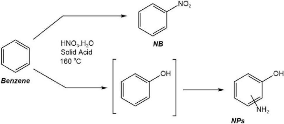
The synthesis of nitrobenzene has been carried out using conventional methods. This method involves using liquid concentrated sulfuric acid as a homogeneous catalyst in the benzene nitration. The sulfuric acid functions to protonate HNO3 into an active electrophilic species, namely the nitronium cation, whereby nitric acid is the titrating agent. However, this method is considered unselective because H2SO4 can cause water dehydration, thus requiring regeneration through removing water. In addition, this regeneration requires a large amount of energy and is susceptible to environmental problems.5-7)Fig. 1 shows the nitration of benzene using a homogeneous catalyst forms nitrophenol as a by-product, in high concentrations. Separation of nitrophenol from nitrobenzene in the product is carried out by gradual washing with alkaline, which can be costly, thus not economical.8)
Nitrobenzene can be synthesized through the nitration process using sulfuric acid and aromatic compounds such as benzene. In the benzene nitration reaction, nitric acid acts as a nitrating agent, while sulfuric acid acts as a catalyst to protonate HNO3 molecules to forming an active electrophilic species, namely nitronium cation (NO2+).9,10) This process is not considered environmentally friendly due to the sulfuric acid forms a bond with water, which causes nitric acid nitration to not be optimal. Thus, regeneration through the removal of water is required. Such operations require a lot of energy and are prone to environmental problems. To reduce energy use, this process can be carried out using a batch reactor and a heterogeneous acid catalyst.11,12)
A solid acid catalyst can be used in place of sulfuric acid to make the nitration process more environmentally friendly.6) Heterogeneous catalysts are advantageous in that they are stable, easily separated, and considered more economical.13,14) Silica is a compound that can be found in nature like granite, rock, and other materials. Silica is commonly used as a catalyst. Silica can increase porosity and catalyst activity due to the good thermal stability and porosity, which would result in the conversion of more products. Silica catalyst can be synthesized using the TEOS precursor through the sol-gel method. Silica synthesized from TEOS can produce silica without impurities, whereas the sol-gel method can produce a catalyst with a large surface area.15)
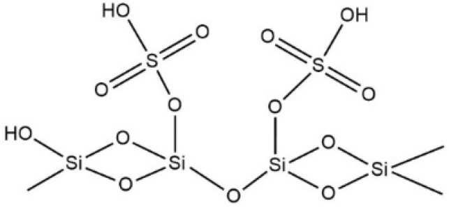
Silica can be modified to improve its catalytic performance. Sulfated silica is one of the modified forms of silica (Fig. 2). The wet impregnation method with silica and sulfuric acid solution can be used to synthesize sulfated silica catalyst. Furthermore, the sulfate process on silica will increase its polarity because of the very polar and reactive nature of sulfuric acid.16) The SO42- ion impregnation on the silica surface can increase the acidity and catalytic activity of the catalyst due to the presence of Bronsted and Lewis acid sites.17,18) Wijaya et al.17) who synthesized catalyst SO4/SiO2 for the hydrocracking used cooking oil into biofuel, reported on the formation of Bronsted and Lewis acid sites on the silica surface, which acted as active sites in increasing the catalytic activity of SiO2 catalysts. The conversion rate of biofuel products was 72.47 %. Based on the excellent properties of the H2SO4/SiO2 catalyst, this research was conducted to examine the H2SO4/SiO2 as an alternative catalyst in the nitration process of benzene.
In addition, the process of nitrobenzene production was converted in a microwave batch reactor with a closed system that uses electromagnetic wave radiation as a source of heat energy.17) The H2SO4/SiO2 catalyst will interact with the reactant (benzene) in the nitration process when exposed to microwaves. Microwaves will cause the catalyst to release sulfate groups, which will then react with HNO3 to form nitronium cations. The use of microwaves in the nitration reaction is intended to minimize the amount of time and energy required for the nitration reaction process.19,20) This study is focused on the synthesis of nitrobenzene from benzene using microwave batch reactor with the help of H2SO4/SiO2 heterogeneous catalyst with good catalytic activity properties.
2. Experimental
2.1. Materials
The materials used in this study were tetraethyl orthosilicate (TEOS) (Sigma-Aldrich, Germany), 37 % hydrochloric acid (Merck, Germany), ethanol (Merck, Germany), methanol (Merck, Germany), 98 % sulfuric acid (H2SO4) (Merck, Germany), 65 % nitric acid (HNO3) and benzene from smart lab (Semarang, Indonesia).
2.2. Catalyst synthesis and nitrobenzene production
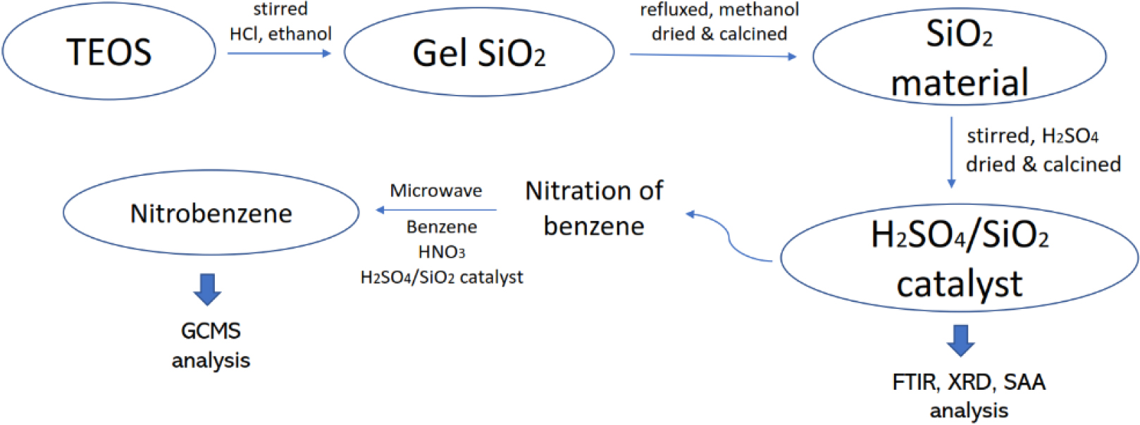
The first thing to do in this research was to synthesize SiO2 material, using the sol-gel method, which will become a supporting agent for the H2SO4/SiO2 catalyst through impregnation of 98 % H2SO4 solution. This H2SO4/SiO2 catalyst plays a role in the nitration reaction to convert benzene to nitrobenzene. Furthermore, SiO2, H2SO4/SiO2 catalysts and nitrobenzene products were characterized with various types of characterization that support the data of this study. The research mechanism is shown in Fig. 3.
2.2.1. SiO2 synthesis from TEOS
16.8 mL of tetraethyl orthosilicate (TEOS) was added with 30 mL of ethanol and 30 mL of 2 M HCl, then stirred at 80 °C to form a transparent gel. The gel formed was washed with distilled water to eliminate Cl- ions and then put in an oven at 100 °C for 3 h. Next, the solid gel was refluxed in 50 mL methanol for 72 h. The resulting solution was then centrifuged at 2,000 rpm for 20 minutes. The precipitate obtained from the centrifugation was oven-dried at 100 °C to form a dry solid. The solid obtained was then calcined at 600 °C for 4 h, sieved through a 100-mesh sieve.
2.2.2. H2SO4/SiO2 catalyst synthesis
H2SO4/SiO2 catalyst was prepared by adding 100 mL H2SO4 solution to SiO2 (from the previous step). The mixture was stirred for 1 h at room temperature. Then, the suspension was centrifuged at 2,000 rpm for 20 minutes. The precipitate produced after centrifugation was dried in an oven at 100 °C to form a dry solid. The solid obtained was then calcined at a temperature of 600 °C for 4 h, sieved through an 80-mesh sieve. The catalyst was then analyzed using FTIR, XRD, and SAA instruments.
2.3. Conversion benzene into nitrobenzene
The synthesis of nitrobenzene was carried out in a microwave reactor. 5 mL of benzene was added with 15 mL of HNO3 and then placed in a round bottom flask of microwave. Next, the H2SO4/SiO2 catalyst was added with a weight variation of 0.5; 1; and 1.5 g. The nitration process in the microwave reactor was carried out by stirring for 5 h at 60 °C. The mixture was separated by filtration of the filtrate and catalyst. The filtrate had 2 layers whereby the top layer was product, and the bottom layer was the residue (catalyst). Finally, the product was separated again by extraction to obtain nitrobenzene and was analyzed by GCMS and the percentage is calculated using the following formula:
2.4. Catalyst and nitrobenzen peroduct characterization
The catalyst was analyzed using FTIR, XRD, and SAA instruments. FTIR analysis were obtained using Shimadzu Prestige-21, Japan in the range of 4,000~400 cm-1 with the KBr pellet technique. The XRD analysis was performed using the X’pert Pro PANalytical with a Cu X-Ray tube (1.5406 Å). The SAA was measured using NOVA Quantachrome Instrument on the basis of Brunauer-Emmet-Teller (BET) theory from N2 gas adsorption isotherms measured at 77 K. The GC-MS analysis of the products was carried out using Shimadzu QP2010S (Japan) with the RTx-5MS chromatography column with column length of 30 m and helium carrier gas. The analysis and interpretation data was carried out using OriginLab Graphing and Data Analysis.
3. Result and Discussion
3.1. FTIR analysis of H2SO4/SiO2 catalysts
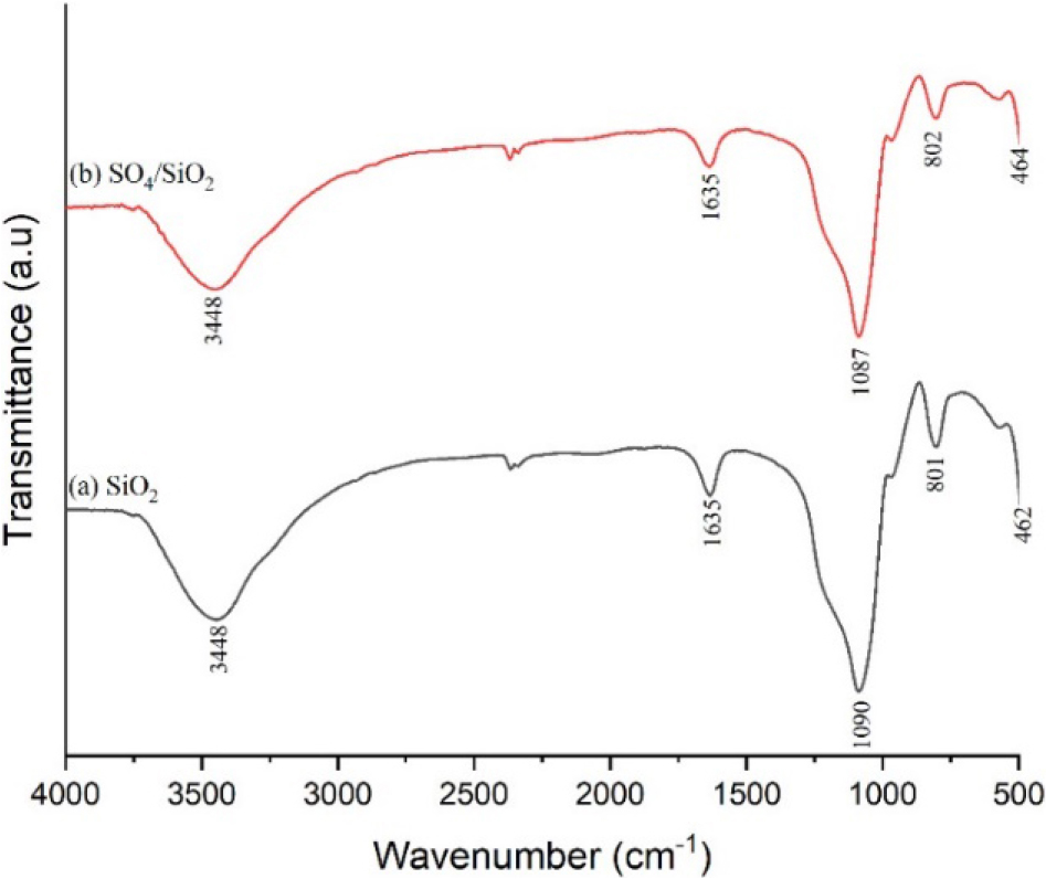
The FTIR spectra of H2SO4/SiO2 catalysts in Fig. 4 show that there was a peak widening in the wave numbers of 3,300 cm-1 to 3,500 cm-1 which indicated the stretching vibrations of O-H and Si-OH from adsorbed water (silanol group). These functional groups were further emphasized by the peak at around 1,635 cm-1 which indicated the deformation of H-O-H as a result of hydrogen bonding interactions with the silanol group.16,17,21)
The specific peak of SiO2 is shown with the sharp peak at the wave number of 1,085 cm-1 indicating the absorption of Si-O asymmetric stretching vibrations from Si-O-Si. The effect of sulfate addition causing the peak overlaps with the S-OH stretching vibration from HSO4-, i.e., sulfated silica ion.22,23)
Zarei et al.24) stated that the asymmetric and symmetric stretching vibration of O=S=O of HSO4- has a wavelength of 1,300 to 1,000 cm-1 and overlaps with the asymmetric stretching vibration of Si-O-Si. As such, the peak widening at 1,300~1,000 cm-1 indicated 3 different vibrations, namely S-OH and O=S=O vibrations from HSO4-, and asymmetric stretching vibrations of Si-O-Si. Moreover, the wave number of around 802 cm-1 indicated the symmetric stretching vibration of the Si-O group, while 462 cm-1 indicated the bending vibration of Si-O.25)
3.2. XRD analysis of H2SO4/SiO2 catalysts
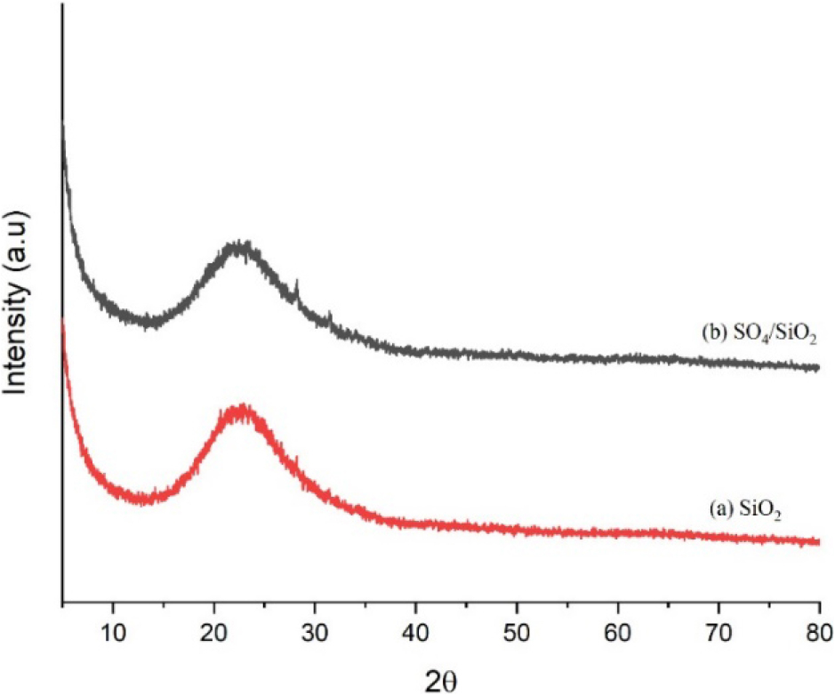
Fig. 5 shows the diffractogram of the SiO2 and H2SO4/SiO2 catalysts. Based on the diffraction patterns of SiO2 and H2SO4/SiO2 catalysts, both had amorphous structures as evident from the absence of sharp peaks.6,21) From the diffractogram it can also be seen that both catalysts had a wide peak at 2θ around 22°. This 2θ value is in accordance with the amorphous silica data contained in JCPDS 39-1425, thus indicating that the SiO2 and H2SO4/SiO2 was successfully formed.
The diffractogram of the catalysts show that there was no change in the structure of silica with the addition of sulfuric acid to activate the silica. In addition, the sulfation process on the silica also reduced the intensity of peak at 22°. This fact due to the successfully of SO42- ions entered to the silica framework to form an amorphous Si-O-S bond that decreased the crystallinity of silica.26) A similar study reported by Wijaya et al.27) used silica sulfated as a catalyst for the diethyl ether production. The presence of SO42- ions on the surface of silica causing the decrease in crystallinity of the silica catalyst.
3.3. SAA analysis
The information about the specific surface area, average pore volume, and total pore volume of SiO2 and H2SO4/SiO2 catalysts based on the N2 adsorption-desorption analysis is shown in the Table 1. The SiO2 catalyst has a surface area of 501,619 m2/g, a pore volume of 2.658 nm, and a pore volume of 0.33 cm3/g. The surface area and pore structure after the sulfation process (H2SO4/SiO2 catalyst) was lower than that of SiO2. This is due to the presence of SO42- ions. The addition of sulfuric acid resulted in the closure of pores on the SiO2 surface resulting in the decrease in the surface area.15,16) Moreover, it also resulted in the decrease in the pore diameter due to the insertion of the sulfate groups into the SiO2 surface pores.21,27) According to Wangsa et al.,11) in the preparation of silica sulfated reported that the sulfation causing the formation of aggregates that blocked the surface of silica causing the decrease in surface area and pore volume.
Table 1.
N2 gas sorption analysis data.
| Catalyst | Specific surface area (m2/g) | Average pore diameter (nm) | Total pore volume (cm3/g) |
| SiO2 | 501.619 | 2.658 | 0.333 |
| H2SO4/SiO2 | 463.736 | 2.645 | 0.307 |
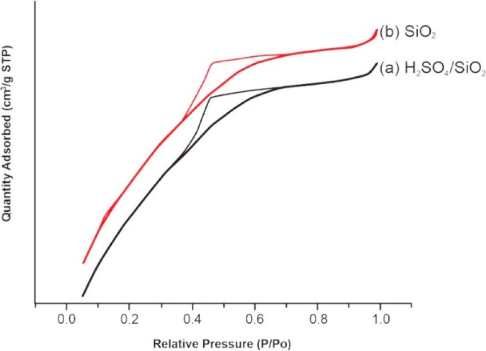
Fig. 6 presents the isotherm graphs for SiO2 and H2SO4/SiO2 catalysts. Based on the graphs, SiO2 and H2SO4/SiO2 materials had type IV isotherm with hysteresis loops indicating H2(a) hysteresis type. The type IV isotherm confirmed the mesoporous material based on the IUPAC isotherm. According to the Sotomayor et al.28) stated that a porous material with type IV isotherm curve and hysteresis H2(a) will a have pores shaped like an ink bottle in the mesoporous size. This ink bottle pore shape can be caused by the closure or blockage of the pore neck and the presence of cavitation-induced evaporation. An example of a type of material having H2(a) hysteresis is silica doped materials. The characteristic of a mesoporous from catalysts also can be confirm based on the pore diameter data (Table 1). The optimum pore distribution of SiO2 and H2SO4/SiO2 is 2.658 and 2.645 nm, respectively. Particles with a diameter pore size of 2~10 nm are classified as mesoporous material.29)
3.4. Conversion of benzene into nitrobenzene
H2SO4/SiO2 catalyst method was tested for its activity to determine the extent of its ability benzene to nitrobenzene. The test was carried out with 33 % (w/w) H2SO4/SiO2 catalyst. The nitration process was carried out using variations in the weight of the solid acid catalyst, 0.5 g, 1 g, and 1.5 g at 60 °C for 5 h using a microwave batch reactor with temperature controlled. In this study, benzene and nitric acid were used in the ratio of 1:3. This is to achieve excess in nitronium ions. With large number of nitronium ions, the high benzene conversion can be produced.
As presented in Table 2, the catalyst weight 0.5; 1; and 1.5 g yielded 1.73 ± 0.024 mL; 2.02 ± 0.024 mL; and 1.98 ± 0.024 mL nitrobenzene, respectively. Based on the results, with the use of 1:3 nitric acid and benzene (15 mL nitric acid and 5 mL benzene), the optimum nitrobenzene yield was obtained using 1 g H2SO4/SiO2 catalyst. In the catalyst variation of 1 g, the highest nitrobenzene produced was 2.05 mL with an average of 2.02 mL. Meanwhile, with 0.5 g H2SO4/SiO2 catalyst used, the conversion was lower than when 1 and 1.5 g of the catalyst were used. This demonstrated that 0.5 g of the catalyst was not sufficient in forming optimum NO2+ from the nitric acid used. The use of 1.5 g of the catalyst gave yield that was not much different to that of 1 g H2SO4/SiO2 catalyst. As such, the use of 1.5 g of the catalyst was considered excessive to form the optimum NO2+ from 15 mL of nitric acid used.
Table 2.
Product formed from the nitration of benzene.
Research on the production of nitrobenzene using different catalysts is known that Gong et al.30) reported that the conversion of benzene to nitrobenzene using a silica catalyst supported Cs2.5H0.5PMo12O40 in the liquid phase resulted in high conversion (95 %) in optimized conditions. Mane et al.1) reported that more than 80 % yield of nitrobenzene was obtained in the vapor phase using a solid acid catalyst Fe/Mo/SiO2. Umbarkar et al.7) also found that using a mesoporous MoO3/SiO2 solid acid catalyst produced more than 90 % of nitrobenzene carried out in the vapor phase. When compared with the H2SO4/SiO2 catalyst in this study, the percentage conversion of benzene to nitrobenzene is still low compared to other catalysts, so optimization is needed under various conditions to increase product yield.
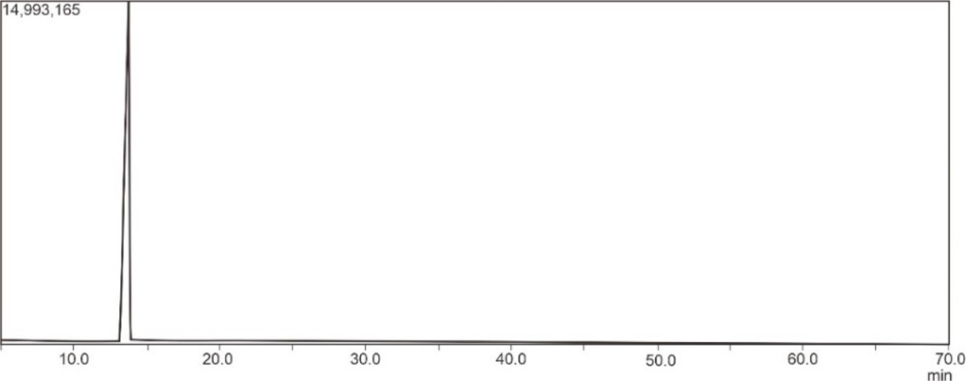
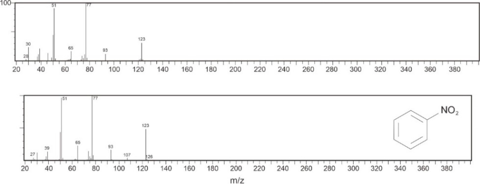
Fig. 7 presents the GC chromatogram of nitrobenzene. In the GC chromatogram, only one peak was formed. This indicated that there is only one type of compound contained in the purified liquid nitrobenzene. Fig. 8 shows the mass spectrum of the purified nitrobenzene and the reference mass spectrum of nitrobenzene. The purified nitrobenzene had similar fragmentations to the reference nitrobenzene. Mass spectrum can be used to predict a synthesized molecule. Based on the research conducted by Chen et al.,31) mass spectrometry showed yields at m/z 123, 77, and 51 for nitrobenzene. Thus, it is concluded that the product synthesized was nitrobenzene and that H2SO4/SiO2 can be used for the synthesis of nitrobenzene.
The reusability of nanosulfated silica as a potential heterogeneous catalyst for the synthesis of nitrobenzene refers to its ability to be reused multiple times without significant loss of catalytic activity or selectivity in the nitrobenzene synthesis reaction. When evaluating the reusability of nanosulfated silica as a catalyst, several factors come into play, one of them is the stability. Our catalyst exhibit stability under the reaction conditions for the synthesis of nitrobenzene. It can maintain its structural integrity, surface properties, and acidity over repeated reaction cycles.
The Table 2, Fig. 7, and Fig. 8 demonstrate that nanosulfated silica nanocatalysts have the potential to convert benzene to nitrobenzene with good stability, activity, and selectivity. The Table 2 provides data and results related to the catalytic performance of nanosulfated silica catalysts in the synthesis of nitrobenzene. It presents information such as selectivity towards nitrobenzene, and stability measurements over multiple reaction cycles. This table shows that the catalyst maintains high selectivity towards nitrobenzene and exhibits good stability, indicating its potential for repeated use.
The result suggests that nanosulfated silica catalysts hold promise for the conversion of benzene to nitrobenzene. They exhibit good stability, high activity, and desirable selectivity.
4. Conclusion
A heterogeneous catalyst based on silica modified with sulfuric acid (sulfation) has the potential to convert benzene to nitrobenzene with good stability, activity and selectivity. The weight of sulfated silica (33 % w/w H2SO4/SiO2) used in the conversion of benzene to nitrobenzene affects the conversion results. The highest conversion of benzene was obtained with the use of 1 g of H2SO4/SiO2 with 40.33 % nitrobenzene conversion. The use of 0.5 g of catalyst was not to be able to produce NO2+ ions optimally, while the use of 1.5 g of catalyst was considered excessive. The use of a microwave batch reactor in the benzene conversion process can be considered to be effective and efficient in reducing energy so that the process taking place may be in accordance with the principles of green chemistry.
