

1. Introduction
DLC coatings have collected a considerable amount of devotion owing to their definite properties such as good chemical inertness, low friction, wear resistance, high hardness, water-resistance, low energy of the surface, temperature battle, anti-adherence of the bacteria, and biocompatibility and water-resistance ability.1-3) The combination of good mechanical properties, high abrasion resistor, chemical lifelessness, and biocompatibility makes DLC coating suitable for usage in the biomedical industry.2,4-6) However, because of the great compressive tension caused by ion bombardment during the deposition process, DLC films often have deprived bonds on some applied substrate, especially biomedical alloys, such as CoCrMo.7,8) To overawed of these restrictions, other elements, for instance, Si, F, O, N, have been familiarized into DLC coatings.3,4,8-10)
Fluorine (F) is one of the greatest incapacitating DLC films to improve abrasion resistance, and water resistance.10-14) Moreover, there are different reports on the increase of inadaptability and reduction of bacterial adhesion of F-DLC sample in comparison to those of uncoated 316 L stainless steel and CoCrMo alloys.6,15) Dawei-Ren16) reported a reduction of bacterial adhesion by 60 % in F-doped DLC coatings, associated to that of the bare 316 L rust proof steel. It was shown that F-DLC coatings are hydrophobic coatings with a water contact angle of over 90°.17) Saitoa et al.18) reported a 4-time increase in the values of contact angle with human blood in F-doped DLC films, compared to that of silicon as the substrate material. F-DLC coatings are fabricated by various deposition approaches for example fluorocarbons and hydrocarbons. Some of the various methods used for incorporating fluorine into DLC coatings include cathodic vacuum arc evaporation, sensitive magnetron sputter, and radio-frequency plasma-boosted CVD (RF-PECVD).
Over the past years, numerous studies have been performed to assess F-DLC properties.17-21) To the best of our knowledge, there is no report on the effect of the F-doping on the hardness and compressive stress of the DLC coatings.
2. Materials and Methods
Silicon (100) and CoCrMo alloy were used as substrates. The CoCrMo samples were prepared by polishing using a 1 µm diamond powder. Then, the CoCrMo samples were cleaned with ethanol, before putting them into the vacuum chamber. As a final cleaning step and for the initiation of the substrate’s surface, a plasma engraving was accomplished (Table 1). For the enhancement of the adhesion between F-DLC coating and CoCrMo samples, a thin TiN interlayer (200 nm) was coated. The films were covered on the substrate utilizing an RF-PECVD apparatus. A mixture of methane (CH4, purity of 99.995 %), carbon tetrafluoride (CF4, purity of 99.995 %), and argon (Ar, purity of 99.995 %) was performed with CH4/Ar and CF4/CH4 flow ratios of 9/1 and 1/9, respectively, for the deposition of DLC and F-DLC coating.
The hydrogen content of the DLC and F-DLC films was measured using ERDA (R.B.S RF, USA). The film composition was also measured by scattering of RBS analysis (R.B.S RF, USA). The chemical bonds of the films were identified by ATR-FTIR (Bruker, USA). Raman scattering (Almega, Sweden) was applied to analyze the atomic arrangement of the films. The hardness (H) and Young’s modulus (E) of the coatings were also characterized by the nanoindentation technique, using CSM Instruments (USA). The remaining stress was evaluated by calculating the curvature radius of the substratum before and after the fabrication of film by the profilometer (RAGA, Iran).22)
3. Results and Discussions
The composition and the hydrogen content of the DLC and F-DLC films were analyzed using RBS and ERDA detectors. The carbon, hydrogen, and fluorine concentrations in the coatings are exhibited in Table 2. The RBS measurements confirmed the incorporation of F in F-DLC film with a concentration of 1.50 at%. Moreover, it can be seen that F-DLC coatings had an inferior hydrogen concentration than DLC coatings. This indicated that F atoms substituted H atoms that link to C atoms in DLC films to form CFx (x<3) groups.23)
Table 2.
The carbon, hydrogen, and fluorine concentrations in DLC and F-DLC films.
| Sample | C at% | F at% | H at% |
| DLC | 74 | - | 26 |
| F-DLC | 74.5 | 1.5 | 24 |
Fig. 1 illustrates the ATR-FTIR analysis of F-DLC coatings at 625~2,000 cm-1, and Table 3 shows a summary of all absorption peaks between carbon and fluorine. As can be observed, the ATR-FTIR peaks consisted of two wide groups in regions of 1,000~1,401 cm-1 and 1,400~1,900 cm-1 matching to CFx(x=1–3) functional groups and C = C vibration modes, respectively.24-26) According to Huang et al.,25) the peak (with low intensity) at 635 cm-1 can be attributed to the CF2 wagging mode. In addition, the band at 730~745 cm-1 is assigned to CF-CF3 bands.25) Two intense absorption bands detected at 1,030 and 1,070 cm-1 were a result of C-F bonds, the high intensity of which can imply that there was plenty of C-F functional group in the F-DLC film. Moreover, low intense peaks at 1,160, 1,220, and 1,450 cm-1 are attributed to CF2 symmetric stretch modes.25-27) In DLC films where C is back-bonded to H, the C = C functional group is usually detected at 1,600 cm-1; however, according to the results of the ERDA test (Table 2) in F-DLC films in which the H atoms are substituted by F atoms, the C = C stretch shifts to higher frequency; accordingly, C = CF stretch modes are observed at the region of 1,608~1,700 cm-1.28) C = C stretching and F2C = C were perceived at 1,700 and 1,720 cm-1, separately. Additionally, the tiny absorbed peak at 2,960 cm-1 was attributed to sp3 CH3 bonds. These results confirm the corporation of F in F-DLC coatings. Furthermore, it was shown that F in F-DLC films was presented mainly in the form of C-Fx(x-1,2) groups which could significantly change the properties of F-DLC films, compared to those of DLC films.
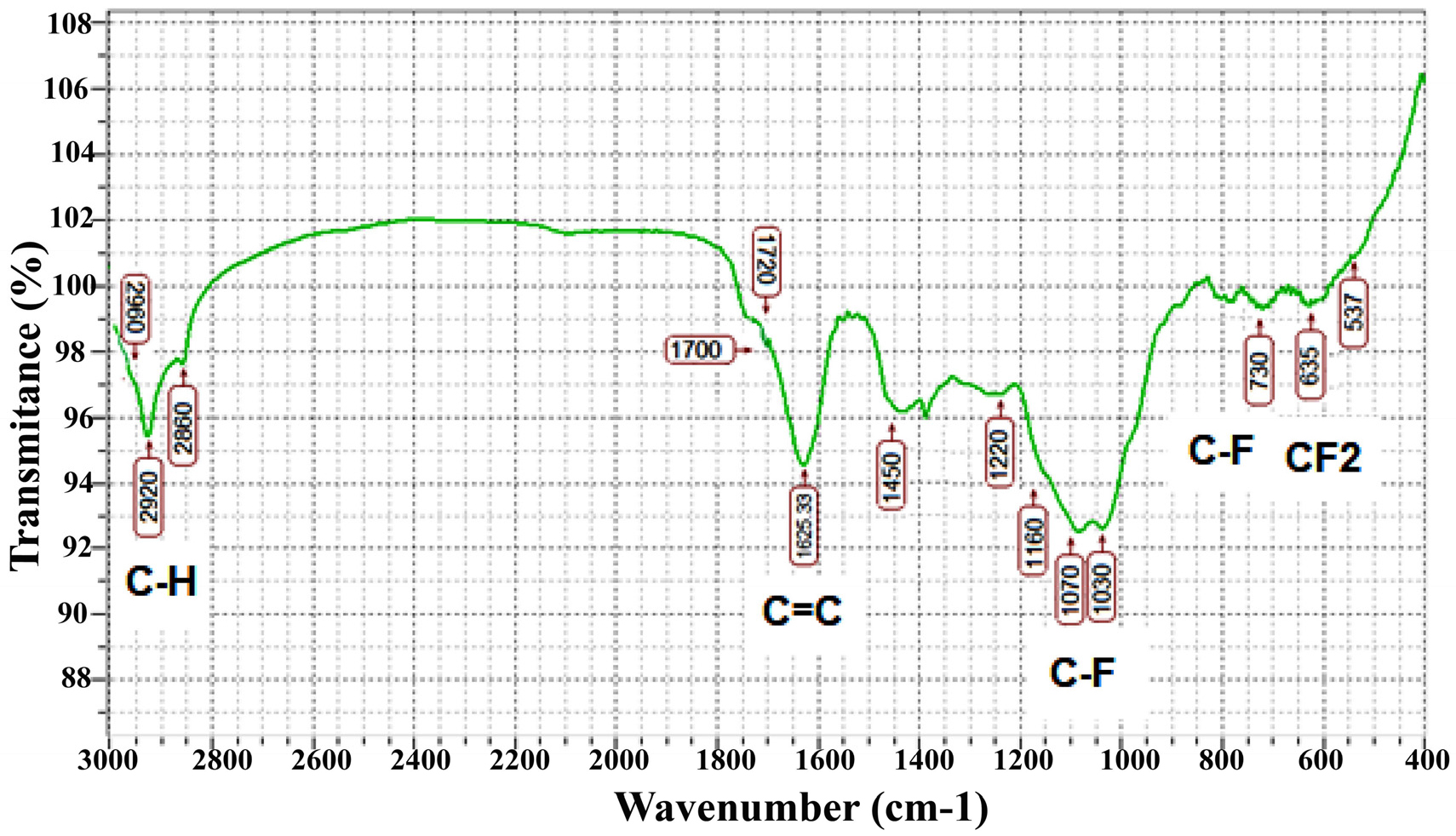
Table 3.
Fig. 2 displays the Raman spectra of the films. The spectra of the coatings were split into D and G bands using two Gaussian diagrams. Then, for the structural characterization of the films and estimation of sp2 content, the peak position, the G peak at FWHM, and the greatness of the D and G bands (ID/IG ratio) were obtained. Table 4 tabulates a summary of the chief features of the Raman scattering of DLC and F-DLC films. According to Table 4, the ID/IG ratio for F-DLC was upper than for DLC coatings. Considering that the G peak is a result of the stretching mode of sp2 locations, although the D band was related to the breathing manner of the sp2 site only in rings, not in chains, the higher ID/IG in F-DLC film implied that the concentration of sp2 ring structure increased in the F-DLC films, compared to that of DLC films.29) In other words, the ID/IG ratio showed the opposite performance with the sp3/sp2 hybrid ratio.
Therefore, a rise in the ID/IG ratio in F-DLC films can be recognized by the improved number of sp2 hybridization and the construction of sp2 of carbon areas.30-34) Moreover, as can be observed in Table 4, the corporation of fluorine in DLC coatings led to the reduction of G-peak width in F-DLC films. G-peak width is a key factor to determine the relative concentration and the size of sp2 clusters and structural order in films; accordingly, the lower G-peak width can be related to the higher concentration of sp2 clusters and higher structural order in the film. Therefore, the results demonstrated a higher concentration of sp2 bonding and more graphitic structure in the F-DLC films, which could lead to lower intrinsic stress in these films, associated with those of the DLC coatings.
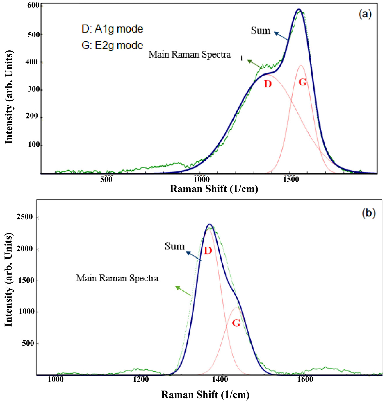
Table 4.
The results of Raman spectroscopy of DLC and F-DLC films.
| Sample | G peak position (cm-1) | D peak position (cm-1) | ID/IG | FWHM (G) (cm-1) |
| DLC | 1,563.40 | 1,374.42 | 0.92 | 71.27 |
| F-DLC | 1,432.55 | 1,365.44 | 2.15 | 34.58 |
For the assessment of the inspiration of the F corporation on the mechanical features and compressive stress in the DLC films, hardness, Young’s modulus, and the amounts of internal stress of both F-DLC and DLC films were evaluated. Table 5 shows the obtained results in this regard. It can be observed that F-DLC had a lower hardness and elasticity, compared to DLC film. Moreover, it can be seen that the addition of fluorine resulted in lower compressive stress in F-DLC films.
Table 5.
Mechanical properties of DLC and F-DLC films.
| Sample | Hardness (GPa) | Young's modulus (GPa) | Compressive stress (GPa) |
| DLC | 11.50 | 109.00 | 1 |
| F-DLC | 8.80 | 97.00 | 0.7 |
The mechanical properties are in a straight line proportionate to the C-C sp3 portions in the microstructure of DLC coating; accordingly, the reduction of the C-C fraction is the main reason for the decline in mechanical properties.31-33) According to the Raman spectroscopy results the introduction of the F produced the alteration of sp3 cross-connected nets into sp2 carbon fields in DLC coatings. Thus, according to the F-DLC films, the drop in the rigidity and elastic modulus was attributed to the breaking of cross-linked C-C sp3 bonds by the merger of the F atoms, which hints at a more open structural arrangement. Ma et al.35) also ascribed the reduction in mechanical properties of F-DLC films to the CF2 quantity in the F-DLC coatings; accordingly, CF2 groups can decrease the stiffness of the C-C network by breaching the carbon network.34,35) Some kind of literature36-58) also reported the reduction in the film mass with amassed doping concentration as the reason for the sharp degradation in the mechanical properties and internal stress of F element doped-DLC coatings. In this study, the results of mechanical properties are in line with the outcomes of Raman scattering, indicating a decrease in the sp3/sp2 ratio in F-DLC films. Regarding the compressive stress in F-DLC coatings, the lessening of interior stress with the amalgamation of F atoms was due to the reduction of the hydrogen content in F-DLC coatings. The presence of F atoms in DLC films caused the construction of HF unstable gas which decreases the content of hydrogen, particularly the unbound hydrogen.37-46) Moreover, lower stress in the F-DLC coatings can be recognized as the decrease in the atomic density of the F-DLC coatings by replacing hydrogen with fluorine. It was stated that an inferior atomic mass and the revolution from a metastable sp3 to an unchanging sp2 conformation to some level can decrease the stiffness of the carbon net and lastly reasons for the fall of the internal stress.23)
4. Conclusion
DLC and F-DLC coatings were covered on CoCrMo substrates by an rf-PECVD system with CH4 and CF4 + CH4 gas combinations, respectively. A higher concentration of graphitic structure in F-DLC films was created which was confirmed by G-scatting mode in Raman analysis. Fluorine incorporation induced a decrease in the compressive stress (1 to 0.7 GPa), hardness (11.5 to 8.8 GPa), and elastic modulus (109 to 97 GPa) of the DLC films. Elastic recoil detection analysis and Rutherford backscattering (ERDA-RBS) results showed that doping with fluorine element reduces the amount of hydrogen in the structure from 26 % to 24 %. According to ATR-FTIR results, fluorine has replaced hydrogen in the structure. On the other hand, according to the results of Raman analysis, doping with fluorine causes a decrease in hybridization sp3 and an increase in hybridization sp2. Therefore, the reduction of the atomic density and the reduction of the unstable phases sp3 happened, and therefore the hardness and compressive stress in the structure are reduced.
