

1. Introduction
In recent years, with the rapid development of society and economy, the contradiction between environmental issues and economic development has intensified. As people's understanding of nature is deeper, the way to develop the economy at the sacrifice of the environment has been found to be impracticable, so people are paying more and more attention to environmental issues.1-4) Among many environmental problems, the problem of water pollution is particular about concern, the development of new technologies to solve water pollution has become an urgent task. Photocatalytic technology has been used to degrade pollutants in water due to its environmental protection, low cost and high efficiency. Many scientists have done many researches in this area.5-10)
Recently, graphite-like carbon nitride (g-C3N4) has been extensive attention as a novel polymer semiconductor photocatalyst because of its suitable band gap, excellent chemical stability, low cost, and easy preparation.11-13) However, g-C3N4 as a photocatalyst has limited its widely application due to its own shortcomings, such as small specific surface area, serious photo-generated electronhole recombination and large band gap.14-17) Scientists have carried out a lot of research on these problems, modifying g-C3N4 nanoparticles, metal/non-metal element doping, forming g-C3N4-based composite system, et al. The photocatalytic activity of g-C3N4 can be improved within a certain range by using these modification methods.18-21)
In traditional carbon-doped carbon nitride modification, there are two main methods, one is grinding the carbonaceous material and g-C3N4 together then heat treatment, the other is to dissolve the carbonaceous substance in an solution containing g-C3N4 or its precursor ,then evaporate the solvent, grind and heat treatment. Obviously, both of these methods have problems of small effective contact area between solid phases, resulting in insufficient reaction. Herein, using the cotton candy that formed by centrifugal spinning of sucrose as a carbon source, the filamentous cotton candy can be sufficiently contacted with thiourea, which greatly increases the effective contact area between the two, and makes the reaction more complete. The modified photocatalyst has a large specific surface area, providing more active sites, thereby improving photocatalytic efficiency.
2. Experiment
2.1 Chemicals
Sucrose, thiourea and Rhodamine B were purchased from Sinopharm Reagent Company. All chemicals were analytical grade and could be used without further purification.
2.2 Preparation of photocatalyst
First, 10g of sucrose was placed in a centrifugal spinning machine to prepare cotton candy, and a certain amount of cotton candy and 5 g of thiourea were fully ground and placed in a covered alumina crucible. The temperature was raised to 550 °C for 2 h, and the heating rate was 5 °C/min, collect the product after ground. The products were named g-CN-X according to the amount of cotton candy added (X is the mass of cotton candy, X = 10, 30, 50, 80, 100, unit mg). The pure carbon nitride was prepared without adding cotton candy and following the above procedure and named g-CN.
2.3 Characterization
X-ray diffraction pattern taken in Bruker D8 Advance equipment with Cu Kα radiation (λ = 1.5406 Å, 40 kV, 40 mA). To obtain the Scanning Electron Microscope images by JSM-7500F. A transmission electron microscopy image was obtained by Hitachi-9000 with an accelerating voltage of 200 KeV. Specific surface area of sample was measured with Brunauer-Emmett-Teller (BET) equation by JW-BK132F at 77 K, and the pore size distribution plots was acquired by Barret Joyner-Halenda (BJH). The UV–vis diffuse reflectance spectra were obtained on a UV–vis spectrophotometer (SolidSpec-3700, Japan) by using BaSO4 as the reference.
2.4 Photocatalytic performance
20 mg of photocatalyst was added to 100 ml of RhB solution (10 mg/L). The adsorption-desorption equilibrium was achieved by dark adsorption for 30 min, and the solution was irradiated with a 300 W xenon lamp with a 420nm cut-off filter. 4 mL of the mixture was taken and the catalyst in the mixture was removed using a 0.22 μm disposable filter every 20 min, the concentrations of pollutants were detected by UV–vis spectrophotometer (UV8000s, yuanxi, China shanghai) with the peak at 554 nm. The UV–vis diffuse reflectance spectra were obtained on a UV–vis spectrophotometer (SolidSpec- 3700, Japan) by using BaSO4 as the reference.
3. Results and Discussion
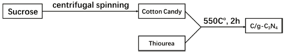
As shown in Fig. 1, a carbon-doped carbon nitride series sample is obtained by centrifugal spinning and calcination strategies, and the filamentous cotton candy can increase the effective contact area with thiourea, thereby making the reaction more complete.
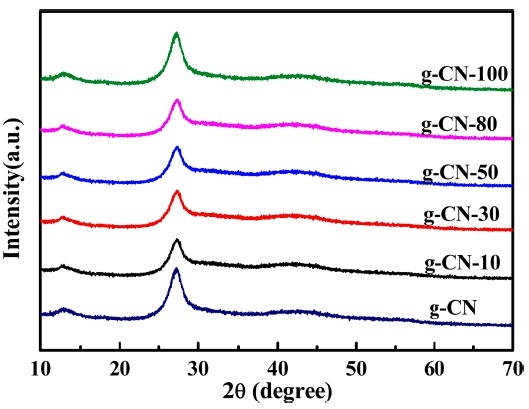
As shown in Fig. 2, all the spectra have obvious characteristic peaks at around 13 and 27.5°, of which the 13.0° peak corresponds to the 3-s-triazine structure (the crystal face index was 100); the 27.5° strong peak indicates the interlayer accumulation characteristic peak of the aromatics (the crystal face index was 002), which proves carbon nitride (g-C3N4) was successfully prepared. As the content of cotton candy increased, the characteristic peak of the crystal plane (002) was obviously weakened, indicating that the carbon doping significantly destroyed the lamellar structure of carbon nitride, which weakened the layer stacking of carbon nitride and improve the specific surface area. As the amount of cotton candy is further increased to 100 mg, the (002) crystal plane peak of carbon nitride was obviously enhanced, indicating that the doping in a certain range can effectively destroy the compact layer stack structure of carbon nitride, which is beneficial to enhance the specific surface area.
As shown in Fig. 3(a), pure carbon nitride is a thick and large lamellar structure. After doping with carbon, the structure of the thin layer has changed, and some pore structure can be seen on the surface [Fig. 3(b)], indicating that g-CN-10 has a relatively large specific surface area, which is also consistent with the XRD results. As shown in Fig. 3(c), as the carbon content increases, the agglomeration of the amorphous carbon causes the bonding of the carbon nitride sheet structure to lower the specific surface area. As shown in Fig. 3(d), a pore structure formed by carbon doping appears on the surface of g-CN-10, further demonstrating that carbon doping enlarges the specific surface area of carbon nitride.
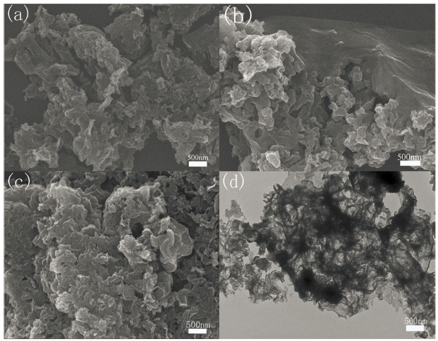
Table 1 shows the specific surface area of the photocatalyst. From the results, as the amount of cotton candy increases, the specific surface area increases and then decreases, which indicates that during the calcination process, the accumulation of amorphous carbon in the carbon nitride sheet layer expands the carbon nitride sheet layer, thereby increasing the carbon nitride sheet layer spacing and expanding the specific surface area of the sample. When the amount of the marshmallow is excessive, amorphous carbon grows and congests on the surface and inside of the carbon nitride sheet to form a lump, thereby reducing the specific surface area and suppressing the catalyst activity. In Fig. 4, the adsorption isotherm is similar to type IV, indicating the presence of mesoporous structures in the photocatalyst. The adsorption isotherm of g-CN-10 moved upward compared to g- C3N4, indicating that carbon doping results in an increase in specific surface area and pore volume.

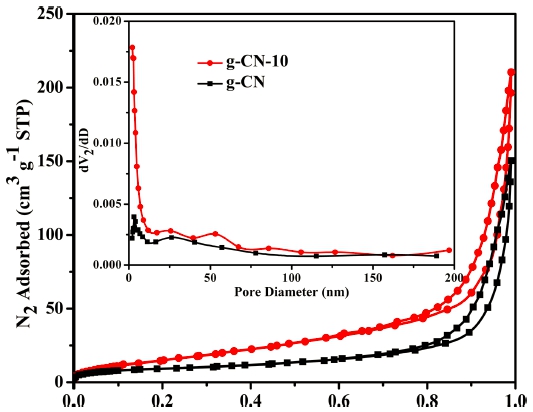
Fig. 4
Nitrogen sorption-desorption isotherms and the pore size distribution curves (inset) of the photocatalysts.
As shown in Fig. 5(a), all the samples responded in the visible range and showed strong absorption. As the amount of cotton candy increased, the absorption capacity of the catalyst for visible light was significantly enhanced. Fig. 5b shows the band gap of g-CN and g-CN-10. The band gap of g-CN-10 is 2.1 eV, which is significantly lower than that of pure carbon nitride 2.7 eV, which greatly enhances separation efficiency of photogenerated carriers.
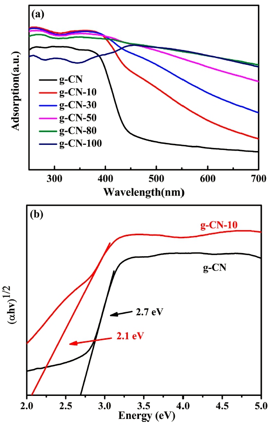
Fig. 6(a) shows the photocatalytic activity of the g-CN and g-CN-X. When no photocatalyst was added, the photodegradation effect of RhB itself was weak and the concentration is basically unchanged. The pure carbon nitride has a degradation efficiency of only 45.4 % after visible light irradiation for 120 min. The modified samples show enhanced photocatalytic performance. The degradation efficiency of g-CN-10 reaches 98.8 % and was two times than that of pure carbon nitride. Fig. 6(b) shows the degradation curve of RhB. The degradation rate of pure carbon nitride is 0.0050 min−1, while the degradation rate of g-CN-10 is 0.0357 min−1, which is 7.14 times than the pure carbon nitrogen, the enhanced photocatalytic rate can be ascribed to the increased specific surface area providing more reactive sites. As shown in Fig. 6(c), three cycles of g-CN-10 test showed that the photodegradation effect was not significantly reduced, indicating that the photocatalyst stability was high.
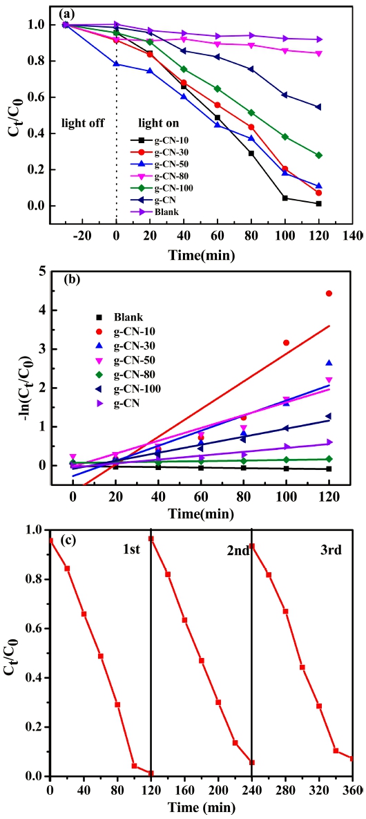
Fig. 6
Diagram of degradation efficiency (a) and degradation rate (b) of g-CN-X, cyclic degradation of g-CN-10 (c), (Blank represents pure RhB).
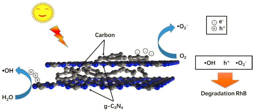
As shown in Fig. 7, when simulated sunlight irradiate onto the surface of the carbon-doped carbon nitride, the photogenerated electrons are excited to transfer from valance band (VB) to conduction band (CB). In addition, the photogenerated electrons are enriched on carbon to react with oxygen to form •O2−, while the photogenerated holes remaining in the valence band are reacts with OH− in water to form •OH. The •O2−, OH−, and photogenerated holes are oxidizing in the system and react with RhB to decompose RhB into small molecules. Since amorphous carbon exists between the surface of the carbon nitride and the sheet, the specific surface area is increased to form more active sites, thereby improving photocatalytic efficiency.
Conclusion
In this paper, a carbon-doped carbonitride photocatalyst was synthesized through a spinning and heat treatment method. The degradation RhB efficiency of the modified photocatalyst g-CN-10 reaches 98.8 % in 2 h, which is twice than that of pure g-C3N4. The enhanced photocatalytic ability ascribed to the increase of specific surface area after carbon doping, which provides more active sites, promotes the process of photocatalytic degradation, and has high photocatalytic stability. The degradation effect is not significantly reduced after three cycles. This strategy provides a new idea for modifying doped carbon nitride.
