1. Introduction
2. Analysis of Failure Case and Discussion
2.1. Lifting mechanism of build platform
2.2. Tilting mechanism of vat
2.3. Blade mechanism used for uniform surface
3. Conclusion
1. Introduction
Ceramic 3D printing technology based on multi-layer fabrication process has been researched in the dentistry field of late.1,2) Some of the recently introduced methods for additive manufacturing of zirconia include stereo lithography apparatus (SLA), digital light processing (DLP), tape casting, and extrusion methods. Photopolymerization-based technologies such as the SLA and DLP ensure high precision, excellent surface quality, and fast output speeds, but they have limitations in material selection.3,4,5,6,7,8) With the help of a doctor blade, tape casting technique guarantees a continuous casting of the ceramic slurry and prevent the separation. However, its material loss rate remains high without a proper means for material reuse. Additive manufacturing using extrusion has a low restriction on fluidity and therefore, can handle materials with high volume fraction. It also has an advantage in obtaining result with high strength, but still needs to overcome shortcomings such as having low precision and slow output speed.9)
Recent research trends involve improving the material properties of ceramic photocurable resins depending on the composition using various additive manufacturing methods.10,11) In the photopolymerization-based process, a slurry prepared by mixing ceramic powder and photocurable resin with a photoinitiator. The slurry absorbs and scatters ultraviolet (UV) light, thereby accelerating the decomposition of the photoinitiator and generating free radicals. These free radicals break the double bonds of the monomers and cause cross-linking bonding.12,13,14,15,16,17) Depending on the position of the UV light source, photocuring-based 3D printing methods can be classified into bottom-up and top-down approaches. The schematic diagram for both approaches is shown in Fig. 1. In the bottom-up approach, the UV light source is positioned at the bottom. The building platform is moved downward, controlling the slurry thickness to a certain level, and the slurry between the lower film and building platform is cured using UV light. The cured layer is then removed from the film, attached to the building platform, and moved upward. This process is repeated to perform 3D printing lamination.18,19) In the top-down approach, curing is performed by exposing the UV light source from the top to bottom. After curing, the building platform moves downward by a distance equivalent to the thickness of previously cured layer. The next layer of slurry is leveled to a certain extent, and lamination continues.
Optimization of the composition is essential for improving the material properties of the final green body. It is also crucial to address problems that occur while actual ceramics additive manufacturing takes place. Nonetheless, there has been insufficient discussion on how to handle such problems. In this study, alumina additive manufacturing was classified into the lifting type (LT) of the build platform, tilting type (TT) of the vat, and blade movement type (BT) as shown in Fig. 2 to discuss problems that occur when alumina suspension slurry is applied to 3D printing. Problems with manufacturing were analyzed according to each driving method, and other analyses were conducted based on DLP.
2. Analysis of Failure Case and Discussion
2.1. Lifting mechanism of build platform
LT manufacturing, generally applied to DLP and SLA, achieves material supply and fluidity through the repeated up and down movements of the platform to add each new layer. A slurry tank is positioned at the bottom of the platform, and the surface of the slurry tank is generally coated with a polydimethylsiloxane (PDMS) film.
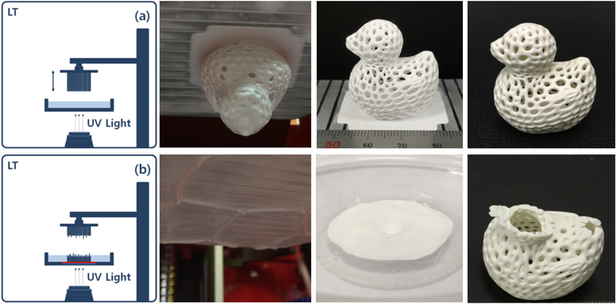
The first failure case of LT is the degradation of PDMS. The chemical formula of PDMS is represented in Fig. 3. PDMS is a transparent and soft polymer with hydrophobic properties and thus prevents photocurable resins from reacting on the surface of the vat. However, consistent photocuring reaction may result in the degradation of PDMS, as it is located between the build platform and vat. The glass transition temperature (Tg) of PDMS ranges from 123.3 to 149.9 °C, and its melting point (Tm) ranges from 217.8 to 235.6 °C.20,21) Commonly used acrylic photocurable resins generate heat during curing, ranging from 80 to 140 °C depending on the polymer components. It seems that some of the PDMS surface are isolated and altered by this heat and thus the surface is degraded while numerous layers are cured on the surface. As some of the degraded surface melt or exhibit adhesive properties, the green body attached to the build platform is pulled downwards. Fig. 4(a) shows the specimen subjected to normal additive manufacturing on the build platform and Fig. 4(b) shows the sample detached from the build platform due to the degradation of the PDMS surface.
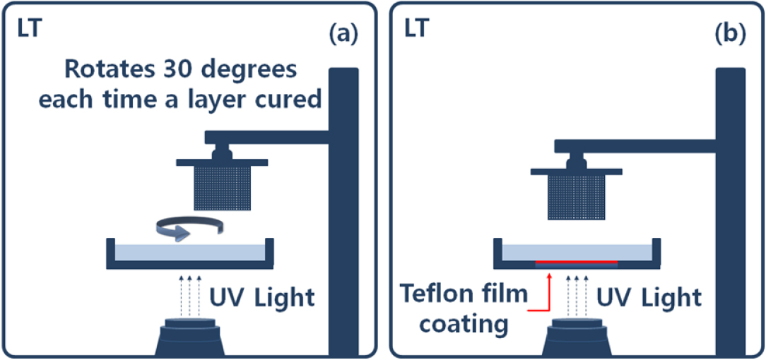
Fig. 5 shows the schematic diagrams of the two methods for addressing the above problem. In Fig. 5(a), the degradation of the PDMS surface is minimized by periodically rotating the vat whenever a layer is added. Such periodic rotation of the vat may also help suppress the separation of alumina slurry. In Fig. 5(b), the vat is fabricated using Teflon film instead of PDMS. Teflon film is a stable compound fabricated through the strong chemical bonding between fluorine and carbon. It is chemically inert, heat resistant, and non-cohesive.22,23) It can also bear a temperature up to 260 °C. These characteristics make it a suitable replacement for PDMS.
The second failure case of LT is the insufficient cure depth and the geometrical overgrowth of the cured surface. These two conditions must be considered together because they occur simultaneously with curing. In alumina slurry used for additive manufacturing, insufficient cure depth and geometrical overgrowth occurs concurrently due to light scattering. The effect of light scattering must be minimized because it cures a larger area than the area previously exposed to the light source. This case may occur in LT, TT, and BT in the same manner, and it is discussed in the LT case.
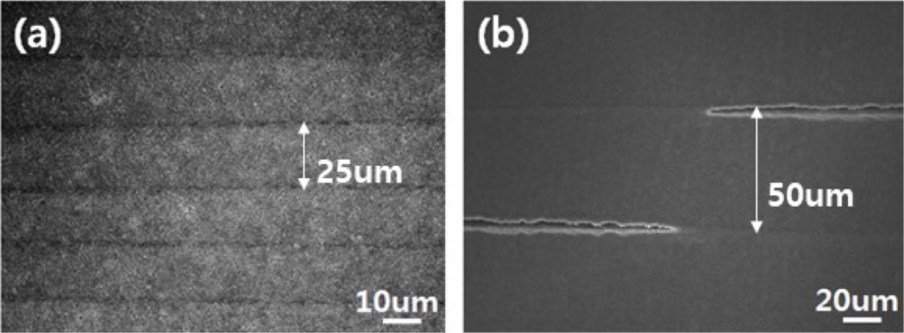
For a 3D printer using LT, it is necessary to set the optical and dynamic parameters to apply alumina slurry appropriately. First, for optical parameters, the curing time is set considering the light quantity and light source value. Short curing time cannot obtain sufficient bonding force between layers due to the low cure depth, while the long curing time causes the geometrical overgrowth of the cured surface.24)Fig. 6 shows the microstructure results in which insufficient cure depth affects bonding force between layers. Fig. 6 show the results when the thickness of each added layer was set to 25 and 50 µm. The cure depth of the 50 vol% alumina slurry used in Fig. 6 has the infiltration capacity of 73.70 ± 5.40 µm when a light-irradiation time is set for 2 s. Although the infiltration capacity is sufficient compared to the set value for the added layer thickness parameter, it may lead to the crack propagation of the green body because the pressure by the detachment of the build platform exists due to the nature of the LT manufacturing. The cracking of the green body may occur in the sintered body in the same manner, causing strength degradation. Second, the dynamic parameter is controlled by adjusting the lifting speed of the build platform. The lifting speed of the platform is generally set within the default parameter value of the 3D printer, but it is possible to modify the g-code value if necessary. As mentioned before, fast detachment must also be considered because it may cause the cracking of layers due to pressure.
2.2. Tilting mechanism of vat
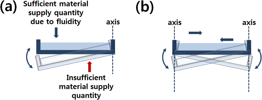
TT manufacturing, used in DLP and SLA, achieves material supply and fluidity through the vertical movements of the fixed axis of a suspension-containing vat, which is repeated as new layers are added in the platform. Fig. 7 shows the schematic diagram presenting the constraints of the TT structured method. Uniaxial and biaxial structures have different material fluidity depending on the number of axes. In the uniaxial tilting, material supply is sufficiently accomplished in area farther from the axis but is limited closer to the axis. In addition, materials with low viscosity are not significantly limited, but materials with high viscosity may significantly affect fluidity.
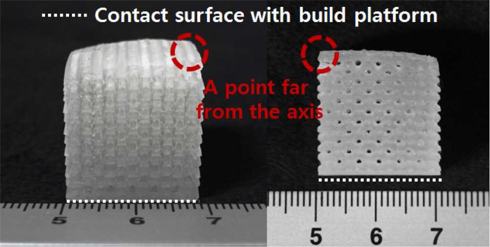
The failure case of TT due to this phenomenon is non-uniform additive manufacturing results. Fig. 8 shows the effect of the uniaxial tilting of the vat on the green body. Uniaxial tilting results in non-uniform manufacturing of the green body.
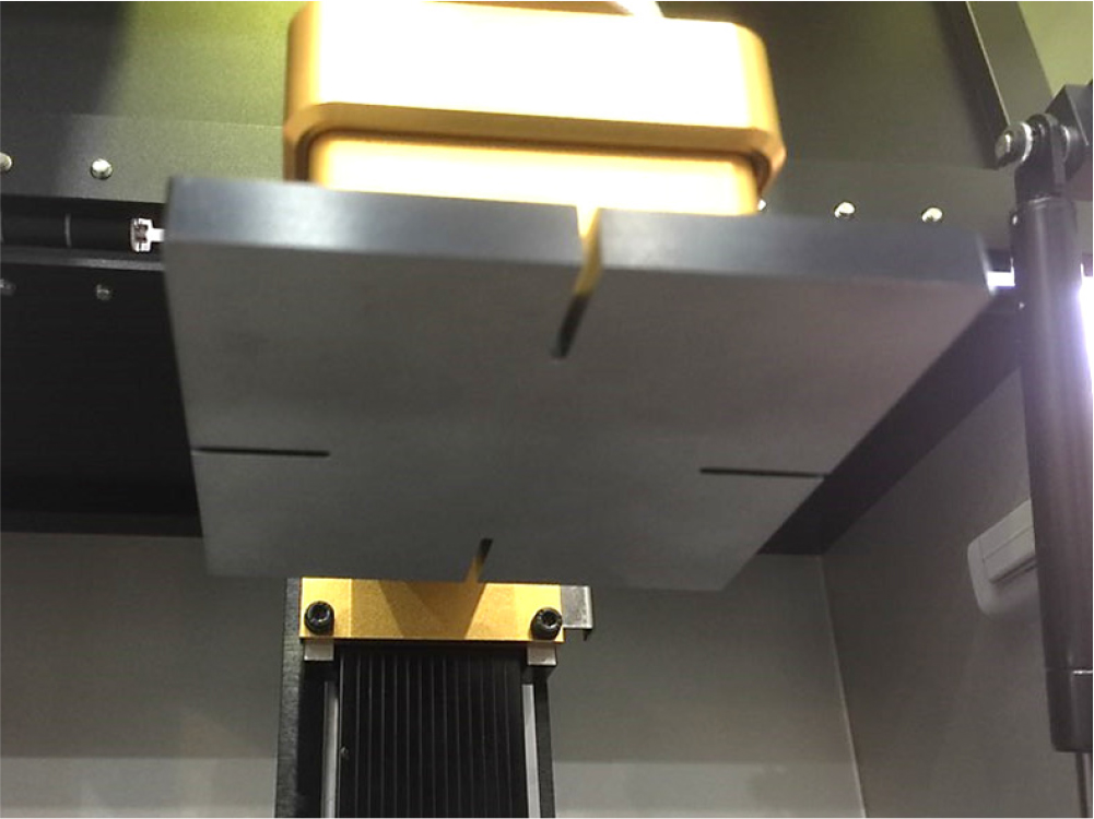
A recently devised solution for such problem is cutting furrows on the surface of the build platform. The furrows shown in Fig. 9 help improve fluidity between the two surfaces and remove some of the surface tension. One or multiple furrows are applied depending on the direction of the axis to complement non-uniform results. Additional experiments on fluidity improvement and surface tension reduction due to furrow-cutting will be conducted in a future study.
2.3. Blade mechanism used for uniform surface
BT manufacturing, similar to tape-casting, supplies material on the uniform surface through the repeated left and right movements of the blade whenever a layer is added to the platform located at the bottom. More commonly adopted method is bottom-up approach, but top-down approach is also possible. The basic dynamic parameters of BT are the up and down movement of the build platform and the left and right movement of the blade. The dynamic parameters control the speed of the blade and adjust the shear stress occurring between the blade surface and the material. The representative material parameter of BT is viscosity. As high viscosity makes it difficult to control the blade and causes overgrowth from light scattering, having appropriate viscosity is very important.
Fig. 10 shows the additive manufacturing step of BT. When the curing of the first layer on the build platform is started, the set area and the other area are separated. Partial curing occurs at the two interfaces due to light scattering. The build platform moves along the z-axis according to the set thickness of the added layer, and the influx of the material begins. Some cured areas collapse due to the influx of the material as well as the movement of the blade, and the next layer is cured. All these steps are repeated, and asymmetric growth occurs due to some collapsed areas.
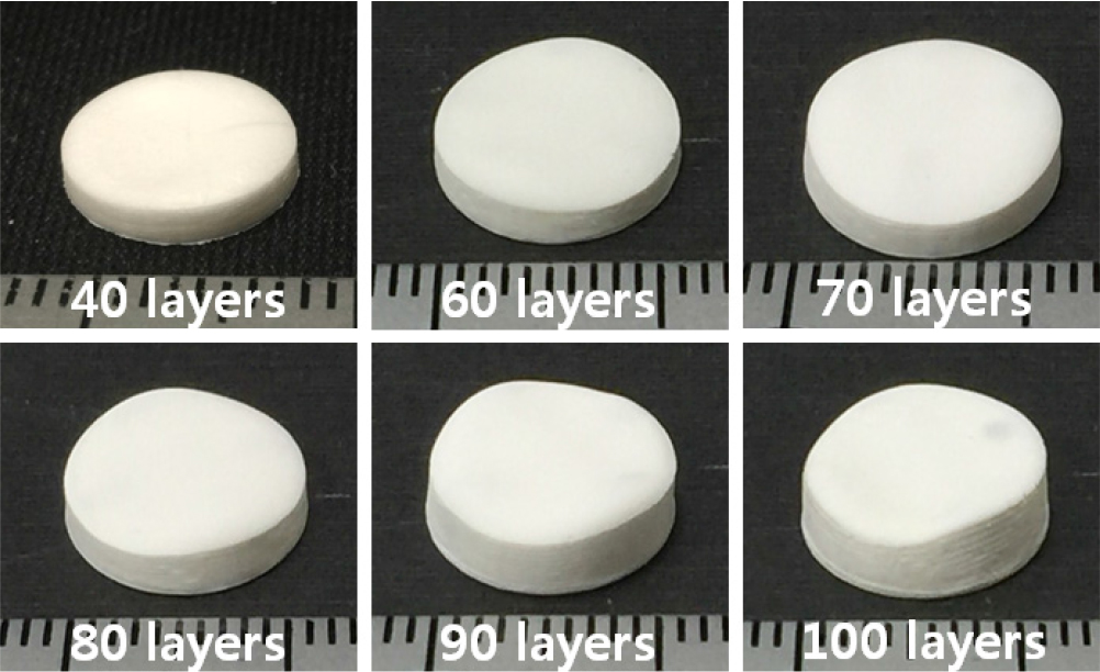
Fig. 11 shows the failure case of BT due to asymmetric growth. Asymmetric accumulation is spotted where layers have been continuously added over areas affected by light scattering. Such an asymmetric growth lacks precision and cannot control the added layer thickness. Higher layer thickness at both ends may cause the specimen to get detached from the build platform by the blade. As it is inevitable for the middle area to have lower layer thickness, areas with insufficient cure depth may start to crack after sintering.
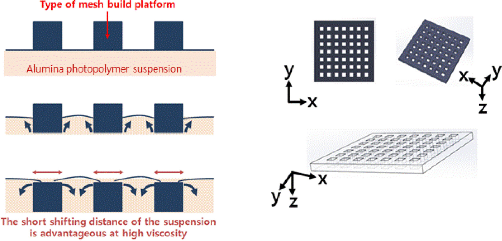
Fig. 12 shows the method for addressing the above problem. The prerequisite is lowering viscosity of suspension, since it ensures an advantage in precision as well as the manufacturing of the green body. Furthermore, high-viscosity alumina suspension fails to guarantee proper material fluidity at the solid build platform.
Porous build platform is a method of minimizing the shifting distance of suspension when it is introduced. Uniform distribution of suspension gives an advantage in dealing with high-viscosity materials because it can help the spreading effect of the blade. However, sufficient spreading of the blade must be assured because geometric deviation may occur in the initial layer due to the inconsistent layer height caused by the surface tension. In addition, to address the segmentation, segregation and sink phenomena of alumina powder that occur in BT manufacturing, the suspension agitation using motor power and the use of ultrasonic waves can be applied. Further experiments are required in the future.
3. Conclusion
This study classified alumina additive manufacturing into LT, TT, and BT, analyzing the possible problems in each type. In the lifting of build platform of DLP approach, the detachment and cracking of the alumina output can be prevented by the control of the cure depth of alumina suspension and bonding force between layers. In addition, replacing the film material coated on the vat and periodically rotating the vat can be effective measures to deter degradation. For vat-tilting type methods, the non-uniform additive manufacturing results of alumina green body can be complemented by adjusting the bidirectionality of the axis and the fluidity of the high-viscosity alumina suspension slurry. For DLP relying on blade movement, its major shortcomings - the detachment of specimen and the non-uniform results - can be mitigated by shortening the shifting distance of the alumina suspension when it’s introduced to the build platform and enabling effective spreading.


