

1. Introduction
Since the first report of Fujishima and Honda in 1972 on the photoelectrochemical(PEC) water splitting using TiO2 as a photoanode,1) tremendous work has been devoted to the investigation of variety of different semiconducting photoanodes for high efficiency solar water splitting. A variety of semiconductor metal oxides such as TiO2, ZnO, BiVO4, WO3 and α-Fe2O3 have been extensively studied as a photoanode for PEC water splitting.2-6) Among these photoanodes, α-Fe2O3 is considered to be a potential candidate due to its low-cost, non-toxicity, earth-abundancy, favorable optical band gap(~2.2 eV), and long-term chemical stability.7,8) Moreover, the valence band edge position (1.6 V vs SCE at pH 14) makes it appropriate for oxygen evolution from water under simulated sunlight.9) A variety of fabrication methods such as hydrothermal1-2) sol-gel,10) sputtering,11) aerosol/spray pyrolysis12) etc. have been employed to prepare α-Fe2O3 thin films. However, the development of a facile, non-toxic and cost-effective solution processing method to prepare high-quality α- Fe2O3 thin films is highly essential. In these regards, Sivula et al.8) reported a solution-based colloidal approach for the preparation of mesoporous α-Fe2O3 thin films. Although, a mesoporous α-Fe2O3 with photocurrent density of 0.56 mA/cm2 was achieved, they employed a multiple steps complex process to fabricate α-Fe2O3 thin films. To overcome the issues associated with the solution-based colloidal approach, Wang et al.6) reported a facile solution phase synthesis of highly photoactive α-Fe2O3 thin films via a deposition-annealing approach using ethanolic Fe precursor solution. Interestingly, significantly improved photocurrent density of 1.78 mA/cm2 at 1.47 V vs. RHE was observed, which is relatively higher than that of a solution-based colloidal approach. Although, significant enhancement in the photocurrent density was achieved by employing deposition-annealing(DA) approach, the fabricated films exhibit a compact nanocrystalline morphology which may affect the PEC performance of α-Fe2O3 thin films. It has been shown that the significant improvement in the PEC performance can be achieved by introducing porous or mesoporous microstructure of thin films.6-8)
Therefore, we report a facile non-toxic solution process based on dimethyl sulfoxide(DMSO) solvent to prepare porous photoactive α-Fe2O3 thin films. This is a simple, versatile method that allows rapid fabrication of α-Fe2O3 thin films with controlled particle size as well as film thickness. Moreover, this method allows the easy doping of foreign elements with high doping level control. This method doesn’t require the use of heavy, expensive and specialized equipments. Thus, α-Fe2O3 thin films prepared using solution-based process in this work showed excellent PEC performance in terms of photocurrent density of 0.78 mA/cm2 at 1.23 V vs. RHE, which is comparable to those of reported values for α-Fe2O3 thin films in the literature.
2. Experimental Section
2.1. Preparation of porous α-Fe2O3 thin films
First of all, a precursor solution was prepared by dissolving 40 mM of ferric chloride(FeCl3, sigma Aldrich) in 10 ml dimethyl sulfoxide(DMSO, sigma Aldrich) solvent at room temperature. Soda-lime glass(SLG) substrates and Fluorine-doped tin oxide(FTO) coated glass substrates (Pilkington TEC glassTM, with resistivity of 6-8 Ω.cm−2) were pre-cleaned via ultra-sonication by sequentially immersing the substrate in deionized water(DIW), ethanol, and acetone for 20 min. in each step to remove some of the organic contamination and dust. The DMSO-based Fe precursor solution was then spin coated onto the SLG and FTO substrates at 2000 rpm for 20 s. The spin coating cycles were repeated 6 times to achieve the desired thickness. After each spin coating cycle, a heat treatment at 260 °C for 5 min. was carried out in order to remove the organic impurities from the films. The as-fabricated films were then subjected to annealing at 550 °C for 2 h in air ambient to form highly crystalize α-Fe2O3 thin films.
2.2. Characterizations
Field-emission scanning electron microscopy(FE-SEM) images were recorded using a FE-SEM(S4800, HITACHI Inc., Japan) operating at 10 kV and 20 mA. The phase formation was confirmed by using a X-ray diffractometer( X'Pert-PRO, PANalytical, Netherlands) operated at 45 kV, 40 mA and at room temperature. X-ray photoelectron spectroscopy(XPS) was further employed to determine the oxidation states of thin films. The binding energies were calibrated using the carbon 1s line at 285.0 eV. The UV-Visible spectra of nanostructures were obtained with Cary 100(Varian, Mulgrave, Australia) spectrometer at room temperature.
PEC performance of thin films were measured using standard three electrode configuration using a potentiostat (CHI Instruments, USA) under simulated sunlight. Fe2O3 thin films were used as working electrodes, Pt as counter electrode and Ag/AgCl as a reference electrode. A Xe lamp was used as a light source at 150W with a light intensity of 100 mW/cm2 with an AM 1.5 filter. N2 gas was continuously bubbled in solution for 30 min. before the measurement to remove any dissolved O2 and therefore suppress the reduction of O2 at the counter electrode.
3. Results and Discussion
3.1. Characterization of thin films
Fig. 1 shows the FE-SEM images of as-deposited (α- FeOOH) and α-Fe2O3 thin films annealed at 550 °C. The dramatic change in the microstructure was observed after annealing treatment at 550 °C. It can be clearly seen that the as-deposited film exhibits the compact and slightly porous microstructure with grain size ranging between 60 to 90 nm(Fig. 1(a)). However, the increment in the porosity was observed after annealing treatment at 550 °C. The annealed α-Fe2O3 thin films showed highly porous microstructure compared to that of as-deposited (α- FeOOH) thin films(Fig. 1(b)). The increased porosity in the annealed thin films could be attributed to the removal of organic compounds during the annealing treatment.
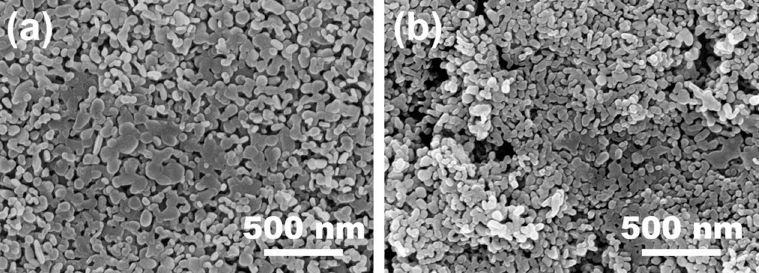
Fig. 1.
FE-SEM images of (a) as-deposited, and (b) annealed α-Fe2O3 thin films. All scale bars are 500 nm.
The phase formation of α-Fe2O3 thin films deposited onto SLG substrates were further confirmed by XRD pattern, which is as shown in Fig. 2(a). XRD pattern shows a sharp diffraction at 33.1° and 35.5° corresponding to (104) and (110) planes of α-Fe2O3 (JCPDS No. 01- 072-0469). Several other weak diffraction peaks at 23.9, 40.81, 49.43, 53.92, 57.55, 62.34, and 64.02 correspond to (012), (006), (024), (116), (018), (214), and (300), which further confirmed the formation of phase pure α- Fe2O3.13) The peak along (104) showed the higher intensity, which indicates that the α-Fe2O3 nanoparticles are oriented in the 104 direction. Furthermore, the average crystallite size was calculated from the broadening of the (104) diffraction peak by Scherrer equation, which is found to be ~28 nm. An XPS was further recorded to determine the oxidation state of Fe in α-Fe2O3 thin films prepared using solution process and is shown in Fig. 2(b). The Fe 2p core-level spectrum shows the binding energy peaks at 710.2 eV and 725.2 eV, which corresponds to the Fe 2p3/2 and Fe 2p1/2, respectively. A satellite peak associated with Fe 2p3/2 at ~718.3 eV, which further confirm the formation of α-Fe2O3.14)
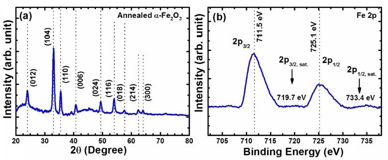
Fig. 2.
Structural characterization of annealed α-Fe2O3 thin films. (a) XRD pattern, (b) Fe 2p core-level XPS spectrum.
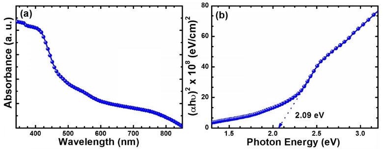
The UV-Vis spectroscopy was further employed to determine the optical absorption and band gap energy of α-Fe2O3. It should be noted that α-Fe2O3 deposited by a facile solution process was translucent and are reddish in appearance. Fig. 3(a) shows the optical absorption spectrum of α-Fe2O3 thin film, which indicates that the α- Fe2O3 thin film exhibits the absorption in visible region. It is also observed that absorption gradually decreased with the wavelength and becomes linear in the wavelength region after ~600 nm. Furthermore, the optical band gap was estimated from the intercept of extrapolating the linear fit from the plot of (αhν)2 vs photon energy(Fig. 3(b)). The band gap energy of α-Fe2O3 was estimated to be ~2.09 eV, which agrees well with the previously reported values in the literature.15,16)
3.2. Photoelectrochemical(PEC) Performance
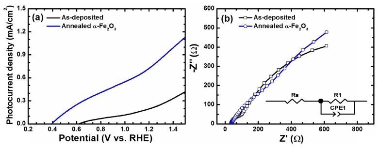
The effectiveness of this DMSO-based solution process for the preparation of α-Fe2O3 thin films were further investigated by the solar water splitting activity of the α- Fe2O3 photoanodes. The PEC performance of as-deposited and annealed α-Fe2O3 photoanodes were measured in 1 M NaOH aqueous electrolyte(pH 13.6) under simulated sunlight. The current density(J) as a function of applied potential(V) plots under dark and in simulated sunlight is shown in Fig. 4(a). The dark J-V curves for both the sample shows the negligible current density over the entire applied potential range. Upon illumination, the asdeposited film showed a very low photocurrent density value of ~0.23 mA/cm2 at 1.23 V vs. RHE. This low current density could be attributed to the poor absorption of light and crystallinity of the photoanodes. Interestingly, the annealing treatment at 550 °C resulted into the significant enhancement in the photocurrent density value to 0.78 mA/cm2 at 1.23 V(vs. RHE), which is about 3.4 times to that of as-deposited thin films. The improved photocurrent density could be attributed to the high crystallinity and improved porosity of the microstructure with interconnected nanoparticles due to annealing treatment at higher temperature. To shed a light on the enhanced photocurrent density, electrochemical impedance spectroscopy(EIS) measurements were conducted at 1.23 V vs. RHE under AM 1.5G illumination. Fig. 4(b) shows the Nyquist plots for as-deposited and annealed thin films. The experimental data was fitted to an RC-circuit model containing a resistor and a capacitor using an equivalent circuit as shown in the inset of Fig. 4(b). It is observed that the annealed thin films exhibited lower series resistance(Rs) of ~61 Ω.cm2 and charge transfer resistance(Rct) of ~253 Ω.cm2 compared to that of asdeposited sample(Rs = 84 Ω.cm2 and Rct = 613 Ω.cm2). This suggests that the annealing treatment enhanced the crystallinity as well as microstructure of α-Fe2O3, which promotes the efficient charge transfer rate and suppress the charge carrier recombination of photogenerated hole and electron.7,8,13) These results suggest that the α-Fe2O3 thin films with high crystallinity and porous microstructure play a key role in enhancing the PEC performance. Thus, it is reasonable to conclude that the DMSO-based solution process may be promising methods to prepare the highly porous photoactive α-Fe2O3 photoanodes. Although, the obtained photocurrent in this study is comparatively lower than the reported values, further improvements are expected after thorough optimization of preparative parameters, additional doping of foreign elements, surface passivation with catalysts etc.
4. Conclusions
In this work, we have demonstrated a facile DMSObased solution process for the preparation of porous α- Fe2O3 thin films, which exhibited relatively high photocurrent density of 0.78 mA/cm2 at 1.23 V vs. RHE. The enhanced photocurrent density of α-Fe2O3 is attributed to the improved crystallinity and porosity of α-Fe2O3 thin films after annealing at 550 °C. The cause of this significant enhancement in the annealed thin films as compared to the as-deposited thin films was further correlated by measuring the EIS spectra, which showed that the annealing of thin films suppresses the charge carrier recombination of photogenerated electron and hole and promotes the efficient charge transfer rate. We believe that the performance of porous α-Fe2O3 thin films prepared by using DMSO-based solution process could be enhanced after further modifications.
