

1. Introduction
In recent years, the excessive consumption of non-renewable fossil fuels has driven a massive need to meet the demands of sustainable development in modern society through the discovery of green, renewable energy sources.1) Lithium ion batteries (LIBs), noted for their high working voltage and outstanding long-term cycling ability, have become prevalent in the battery market for portable electronic devices and electric vehicles.2,3) However, limited lithium resources cannot satisfy the demands of large-scale applications, prompting researchers to seek alternatives to LIBs at this stage. Sodium-ion batteries (SIBs), which offer storage performance comparable to lithium-ion batteries, are considered an ideal substitute for lithium due to their abundance and low cost.4,5,6) Nonetheless, SIBs pose certain disadvantages, such as a higher redox potential of Na+/Na0 (-2.71 V) compared to Li+/Li0 (-3.04 V), greater atomic mass (23 g/mol for Na vs. 7 g/mol for Li), and larger ionic radius (1.02 Å for Na vs. 0.76 Å for Li), which limit Na diffusion into or out of host materials, thereby affecting the overall kinetics and electrode integrity.7,8,9) Therefore, identifying suitable electrode materials with superior electrochemical properties is critical to advance the practical application of SIBs.
Cathode materials are crucial in SIBs, as they significantly influence the batteries’ energy density, cycling stability, and cost-effectiveness.10) Currently, research on sodium ion cathode materials is focused in four main areas: layered transition metal oxides (NaNi1/3Fe1/3Mn1/3O2,11) Na3Ni2SbO6,12) etc.); polyanionic compounds (Na2OV2O3P2O5,13) NaFe2-xVx(PO4)(SO4)2,14) Na2Fe2(SO4)3,15) etc.); Prussian blue analogs (Na2-xMn[Fe(CN)6],16) Na0.54Co1.23[Fe(CN)6]・7.6H2O,17) etc.); and organic cathodes (Na2AQ26DS,18) AQ26ONa,19) etc). Polyanionic compounds, such as phosphates and sulfates, employed as cathode materials, exhibit combined advantages of elevated operating voltage plateaus and exceptional cycling stability, attributable to their robust framework structures that minimize lattice distortion during Na+ (de)intercalation.20,21) However, cathode materials are impeded by low electrical conductivity and specific capacity.22) Currently, several effective strategies have been employed to enhance their electrochemical performance, including doping with cations, coating the material surface, and reducing particle sizes to the nanoscale. Studies have demonstrated that the integration of cobalt ions (Co2+) into the cation site markedly enhances the sodium ion diffusion dynamics and optimizes the overall electrochemical properties of these materials.23,24)
In this study, the crystal structure of NaFe2PO4(SO4)2 (NFPS) was optimized through Co2+ doping at alkali metal sites using a facile solid-state approach, resulting in the synthesis of a series of Co-substituted cathode materials Na1-xCoxFe2PO4(SO4)2 (x = 0, 0.06, 0.08, 0.10). XPS characterization revealed that the introduction of cobalt sources into the samples generated a higher concentration of oxygen vacancies. Subsequently, half-cells were assembled in an argon-filled glove box with metallic sodium serving as the working electrode (anode). The electrochemical performance of all batteries was assessed using a LAND CT3001A battery testing system. Among these, NFPS-Co0.08 exhibits notable performance advantages, including enhanced discharge specific capacity and improved cycle stability, suggesting that the increased oxygen vacancy concentration contributes to superior electrochemical properties. Additionally, cyclic voltammetry (CV) and galvanostatic intermittent titration technique (GITT) were employed to investigate the dynamic behaviors of two cathode materials and the superior diffusion capability of Na0.84Co0.08Fe2PO4(SO4)2.
2. Experimental Procedure
2.1. Chemicals
Sodium nitrate (NaNO3) was sourced from Tianjin Bodi Chemicals Co., Ltd. Ammonium dihydrogen phosphate (NH4H2PO4) and ferric nitrate (Fe(NO3)3) were obtained from Shanghai Aladdin Biochemical Technology Co., Ltd. Cobaltous nitrate (Co(NO3)2) and Ammonium sulfate ((NH4)2SO4) were acquired from Shanghai Macklin Biochemical Co., Ltd. Conductive carbon black (SP), polytetrafluoroethylene (PTFE), and the electrolyte were procured from Guangdong Canrud New Energy Technology Co., Ltd. The electrolyte comprised 1 M NaClO4 dissolved in a mixture of propylene carbonate (PC) and 10 wt% fluoroethylene carbonate (FEC).
2.2. Preparation
The synthetic procedure for transition metal-doped Na1-2x CoxFe2PO4(SO4)2 (x = 0, 0.06, 0.08, 0.10) started with dissolving stoichiometric amounts of NaNO3 (0.84 mol, 0.1428 g for NFPS Co0.08), NH4H2PO4 (1 mol, 0.2301 g), Co(NO3)2 (0.08 mol, 0.0466 g for NFPS-Co0.08), (NH4)2SO4 (2 mol, 0.5286 g), Fe(NO3)3 (2 mol, 1.616 g) in 50 mL of ultra-pure water in a beaker. Subsequent sonication and stirring at 80 °C in an oil bath facilitated the evaporation of water. The resulting orange amorphous product was heated at 475 °C for 18 h in a muffle furnace. The final product, NFPS-Co0.08, was obtained by grinding the obtained orange precursor and then calcining in a muffle furnace at 475 °C for 18 h.
Similarly, pure NFPS samples and cobalt-doped NFPS samples (NFPS-Cox), each with varying metal doping levels, were synthesized for comparison.
2.3. Structural characterization
The crystal structures of the synthesized composites were analyzed using Cu Kα radiation X-ray diffraction (XRD, Bruker D8 Advanced, 3 kW). The morphology of the samples was examined using scanning electron microscopy (SEM, Quanta FEG 250) and transmission electron microscopy (TEM, Hitachi HT-7700). The crystal morphology model was generated through simulations on the VESTA software platform. The samples was determined by X-ray photoelectron spectrometry (XPS) using an XSAM 800 apparatus.
2.4. Electrochemical measurement
The composite electrode was fabricated by mixing the active material, SP and PTFE in a mass ratio of 5:4:1. Electrochemical evaluations were performed in hermetically sealed CR2016 coin cells, assembled meticulously in a high-purity argon glovebox (H2O < 0.1 ppm, O2 < 0.1 ppm). The configuration of the cell included metallic sodium as the counter electrode and Whatman GF/D glass microfiber separators.
To promote adequate interaction between the electrolyte and electrodes, all batteries were allowed to rest for 8 hours before further processing. Batteries then underwent constant-current charge/discharge tests using the LAND CT3001A battery test system within a voltage range of 2-4.4 V. CV was performed on a CHI 660C electrochemical workstation within a potential range of 2-4.4 V. The GITT was carried out using the LAND CT3001A testing system in a voltage range of 2-4.4 V at a current density of 25 mA g-1. Each applied galvanostatic current and resting period lasted 10 min and 8 h, respectively. Electrochemical impedance spectroscopy (EIS) measurements were taken using a CHI 660C electrochemical workstation with a frequency range from 105 to 0.1 Hz and an AC amplitude of 5 mV, under open-circuit conditions of 2-4.4 V after stabilizing the system for 30 min to ensure quasi-equilibrium.
3. Results and Discussion
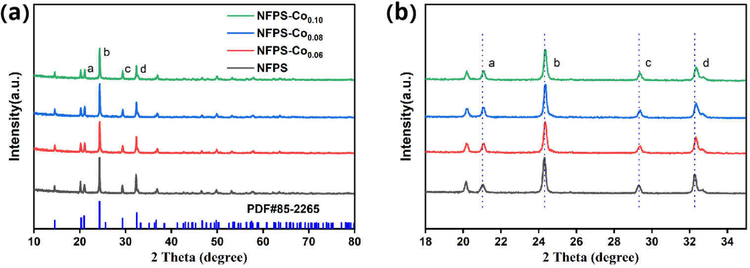
The crystal structure of NFPS is analyzed with NaTi2(PO4)3 serving as a reference, owing to their identical structural frameworks. The diffraction peaks in Fig. 1 show a high degree of correlation with those of NaTi2(PO4)3 (JCPDS No. 85-226525)). XRD analysis demonstrates that introducing Co2+ dopants into the NFPS crystal structure results in no new diffraction peaks, indicating that the Co2+ substitution does not cause significant structural changes.26) A detailed examination of the XRD patterns reveals that the four primary diffraction peaks (labeled a, b, c, d) systematically shift toward higher angles as the Co2+ doping concentration increases, indicating a contraction in the interlayer spacing in accordance with Bragg’s law.27) The reduction in interlayer spacing typically results from internal lattice stresses, such as those induced by dopant ions that possess smaller radii than the host ions, leading to a contraction of the lattice parameters.28,29) The smaller ionic radius of Co2+ compared to Na+ is clearly evidenced, which consistently aligns with the experimental observations.
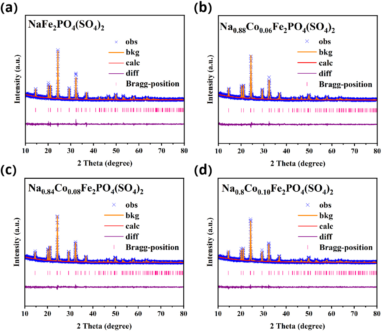
To assess the effect of defect concentration on material properties, the crystal structures of NFPS-Cox (where x = 0, 0.06, 0.08, and 0.10) were analyzed using XRD Rietveld refinement. The corresponding results are displayed in Fig. 2(a), (b), (c), and (d). The observed XRD peaks belong to the trigonal R-3c space group. The refinement reliability factors Rwp = 17.40, 15.86, 15.28, and 14.74, and χ2 = 1.39, 1.32, 1.25, and 1.22, demonstrate excellent agreement between the experimental and calculated patterns.30)
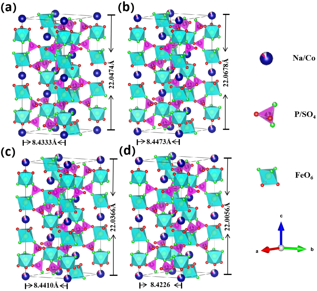
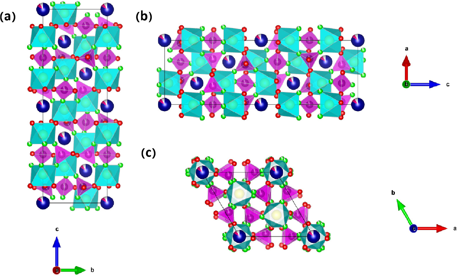
This structure retains the characteristic NASICON (Na- super-ionic conductor) architecture even after partial substitution of Na⁺ ions by Co2+, as depicted in Fig. 3(a), (b), (c), and (d). The three-dimensional crystal framework consists of interconnected PO4/SO4 tetrahedra and FeO6 octahedra, which are interconnected via corner-sharing oxygen atoms, facilitating continuous sodium ion diffusion pathways. Due to the introduction of Co2+, the a and b values (8.43 Å for NFPS, 8.44 Å for NFPS-Co0.08) increase and the c value (22.05 Å for NFPS, 22.04 Å for NFPS-Co0.08) decrease, resulting in an increased cell volume (1357.95 Å3 for NFPS, 1359.76 Å3 for NFPS-Co0.08) which enlarges the diffusion channel of sodium ions, enhancing Na+ dynamics.31) Excessive Co2+ doping negatively impacts the structural integrity of the material.32) The unit cell volume of NFPS-Co0.10 (1351.92 Å3) is significantly smaller than that of NFPS-Co0.08 (1359.76 Å3) and undoped NFPS (1357.95 Å3), indicating that excessive doping may compromise the intrinsic structural stability.33,34)Fig. 4 depicts the crystallographic projections of NFPS-Co0.08 along the a-, b-, and c-axes, highlighting its crystalline structure with alternating FeO6 octahedra and (Na/Co) polyhedral layers.
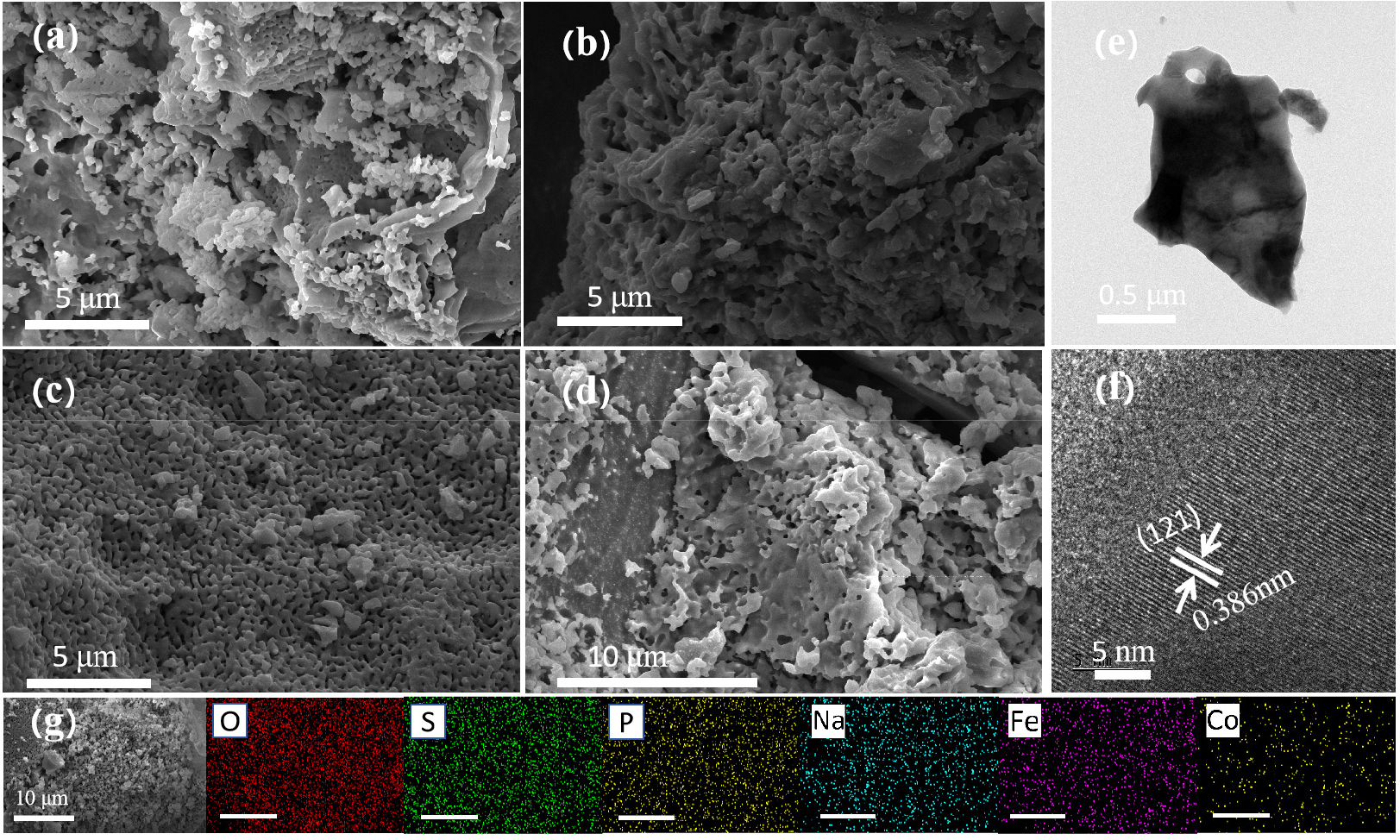
To verify this hypothesis, we initially carried out XRD and TEM analyses to examine the microstructure of the material and assess its impact on the material’s properties. The morphologies of Na1-2xCoxFe2PO4(SO4)2 (x = 0, 0.06, 0.08, 0.10) with different Co2+ doping ratios were characterized using SEM and TEM (Fig. 5). As indicated in Fig. 5(a), (b), (c), and (d), Co2+ doping results in a more uniform pore distribution, thereby enhancing the effective diffusion path of Na+. Simultaneously, an increase in Co2+ concentration changes the specific surface area of the sample. A high specific surface area provides numerous active sites and improves the interfacial contact between the material and electrolyte, thereby enhancing the electrochemical performance of battery materials.35)Fig. 5(e) presents the TEM image of NFPS-Co0.08, where the locally magnified segment reveals lattice fringes with a distance of 0.386 nm, corresponding to the (121) crystallographic plane [Fig. 5(f)]. Moreover, the elemental mappings of NFPS-Co0.08 indicate that the elements Na, Co, Fe, P, S, and O are uniformly distributed, as shown in Fig. 5(g).
To further investigate the impact of specific surface area on battery performance, Brunauer-Emmett-Teller (BET) measurements demonstrated specific surface areas of 7.7395 m2/g for NFPS and 8.2970 m2/g for NFPS-Co0.08 (Table 1). Generally, variations in particle surface area may result from changes in solution composition during the reaction process, influenced by the different annealing temperatures of sodium nitrate and cobalt nitrate.27,36,37,38,39) The increase in specific surface area of the electrode material facilitates a shorter transfer path and a larger effective contact area, which contributes to improved Na+ dynamics.40) However, excessive doping (2.2756 m2/g for NFPS-Co0.10) leads to a reduction in specific surface area that potentially results in decreased sodium ion diffusion channels, culminating in poor performance.
Table 1.
Specific surface area and Pore Size of four samples after N2 adsorption.
| Thermophysical properties | NFPS | NFPS-Co0.06 | NFPS-Co0.08 | NFPS-Co0.10 |
| BET surface area (m2・g-1) | 7.7395 | 6.8905 | 8.2970 | 2.2756 |
| Average pore size (nm) | 4.8762 | 4.9306 | 4.5378 | 3.9765 |
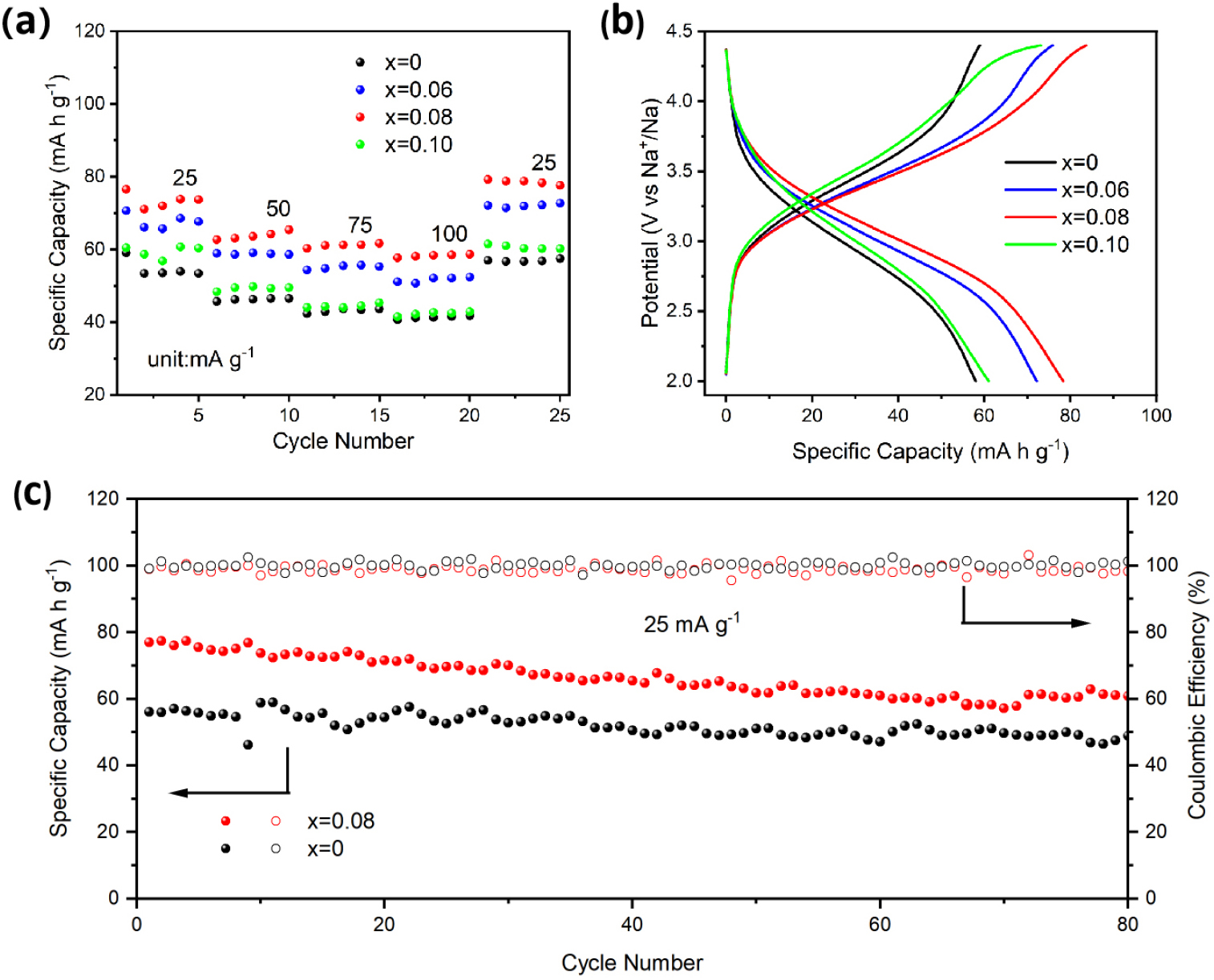
The galvanostatic charge-discharge (GCD) tests were systematically performed to explore the impact of cobalt ion doping on the electrochemical performance of the material. Fig. 6(a) displays the rate performance of four samples of Na1-2xCoxFe2PO4(SO4)2, with x values of 0, 0.06, 0.08, and 0.10. The NFPS-Co0.08 composite showed significant performance advantages within the voltage range of 2-4.4 V; moreover, varying the doping proportions on the battery performance resulted in various degrees of improvement. After restoring the current to 25 mA g-1, the capacity of NFPS-Co0.08 could also be restored to its original state, indicating good reversibility of the material. However, NFPS-Co0.10 displayed a lower discharge specific capacity and significant polarization, likely due to structural impairment from excessive Co2+ doping.41)Fig. 6(b) illustrates the charge-discharge curve of one cycle for the four samples under a potential window range of 2-4.4 V. Here, NFPS-Co0.08 presents a discharge specific capacity of 78.3 mA h g-1, which is 1.35 times that of NFPS. Fig. 6(c) presents the cyclic performance of NFPS and NFPS-Co0.08 at a current density of 25 mA g-1. After 80 cycles, the discharge capacity reached 59.4 mA h g-1, and the coulombic efficiency of NFPS-Co0.08 approached 100 %. In conclusion, the doping strategy significantly improved battery performance, with the NFPS-Co0.08 composite exhibiting superior discharge specific capacity, excellent rate capability, and enhanced cycling stability.
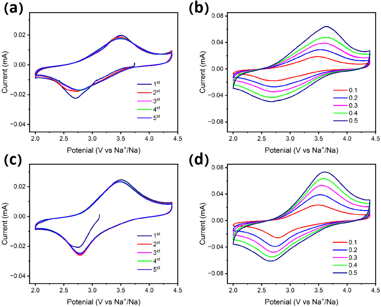
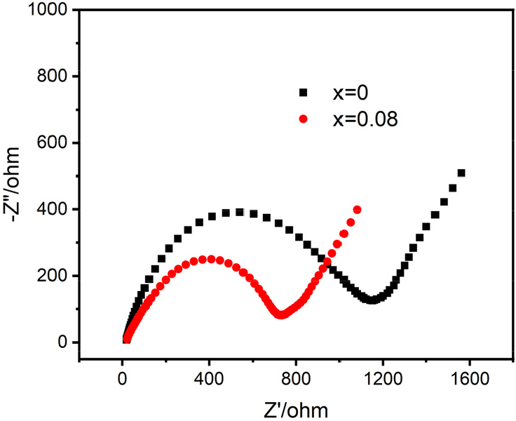
To investigate the effects of doping with Co ions on the structural stability of the material, the same CV test was performed for both NFPS and NFPS-Co0.08 (Fig. 7). Fig. 7(a) and (c) display the CV curves of NFPS and NFPS-Co0.08 for the initial five cycles within a voltage window of 2-4.4 V, with a scan rate of 0.1 mV s-1. Notably, NFPS-Co0.08 demonstrated significantly better curve overlap compared to pristine NFPS, indicating that cobalt doping considerably improves the electrochemical stability of the crystal structure. Fig. 7(b) and (d) illustrate the multi-scan rate CV analyses performed on NFPS and NFPS-Co0.08, respectively, under the same voltage conditions but with scan rates ranging from 0.1 to 0.5 mV s-1. The peak current density increases progressively with sweep rate. Fig. 8 presents the impedance results obtained under open circuit conditions of 2-4.4 V, showing that the impedance of NFPS-Co0.08 is superior to that of NFPS, corroborating the previously measured electrochemical properties.
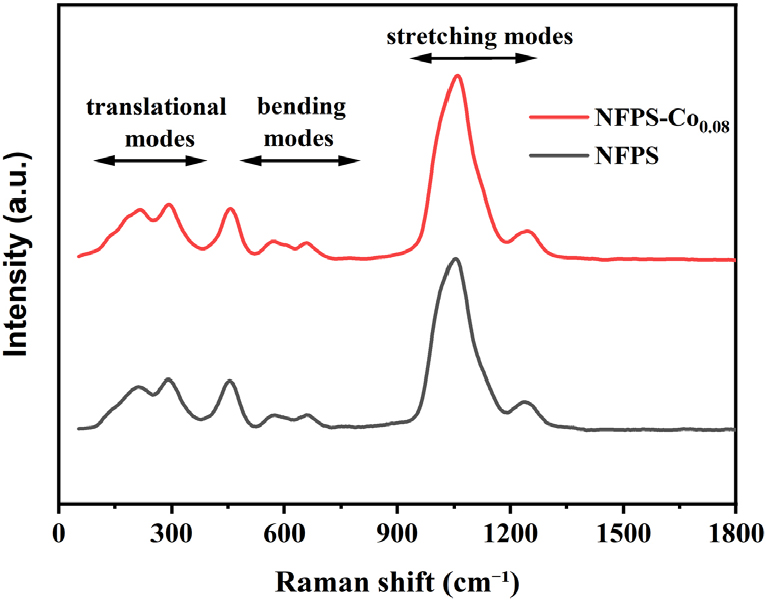
In order to know the existence of phosphate and sulfate groups, the deconvoluted Raman spectrum is presented in Fig. 9. The stretching modes of PO43- and SO42- are within the 900-1,200 cm-1 range, while the bending vibrations are within the 500-800 cm-1 range.8,42,43) All the other small structural vibrations below 400 cm-1 are assigned to the Fe-O based lattice modes.
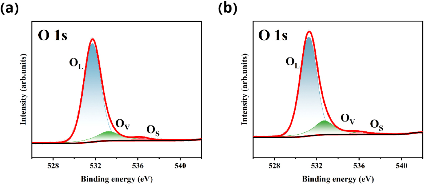
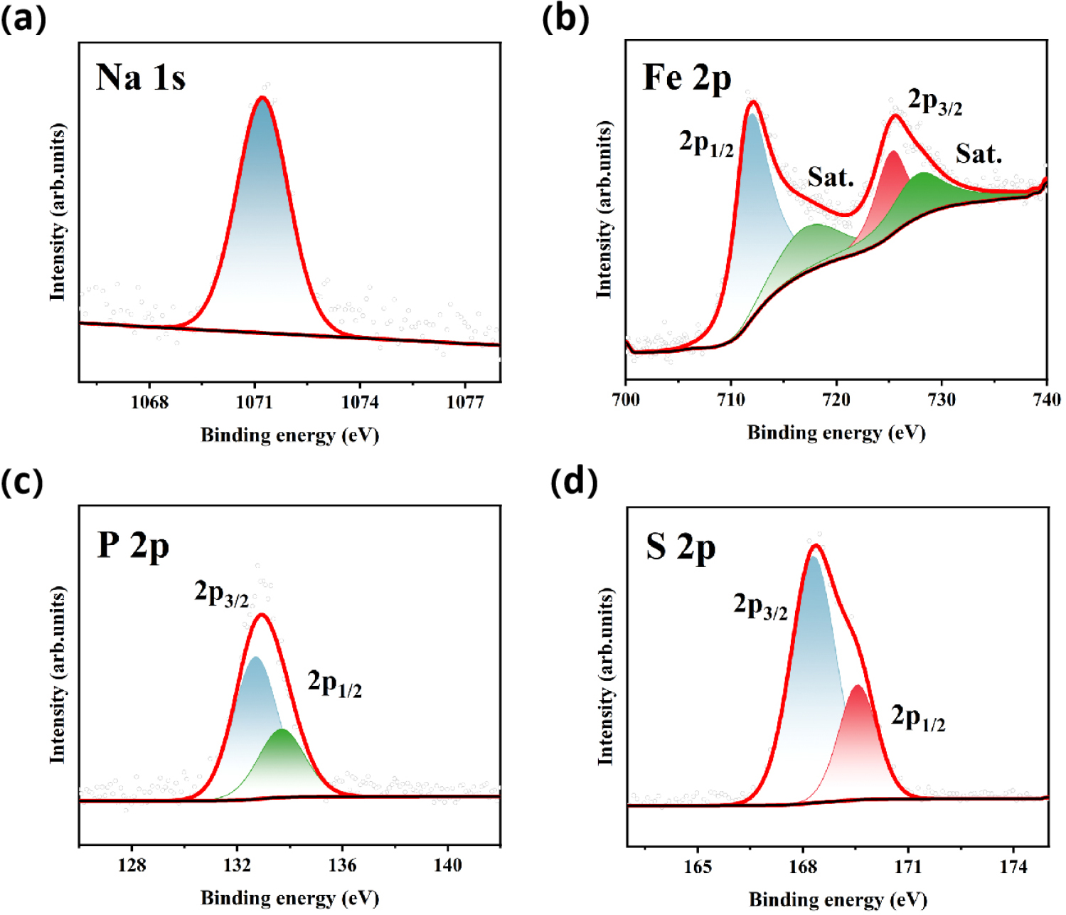
In order to further study the effect of oxygen vacancies on electrochemical performance, in Figs. 10 and 11, we show the core energy level photoelectron spectra of NFPS and NFPS-Co0.08 samples. The calibration of all the spectra is done with respect to the C 1s peak at 284.6 eV. The deconvoluted O 1s spectrum is depicted in Fig. 10(a), revealing the presence of three components located at (i) 531.7 eV (OL), which can be assigned to the lattice O2-; (ii) 533.2 eV (OV) is attributed to the oxygen vacancies (estimated ~15% by taking area under the respective peaks); and (iii) 536.3 eV (OS) corresponding to a surface hydroxyl group (-OH).44) Compared to undoped samples, the increased oxygen vacancy (estimated ~19 % by taking area under the respective peaks) peak area in cobalt-doped samples indicates the generation of more oxygen vacancies.The increase of the peak area ratio of oxygen vacancies improved the electrochemical performance of the cathode material NFPS-Co0.08. Fig. 11(a) displays the Na 1s core level centered at 1071.4 eV, which indicates the monovalent state of sodium. The Fe 2p spectrum, in Fig. 11(b), consists of 2p3/2 and 2p1/2 peaks along with their respective satellite peaks.45) These core-level peaks are observed at 711.6 eV and 725.2 eV with their corresponding satellite features at 717.1 eV and 727.6 eV, which indicate the presence of Fe solely in the trivalent state. In Fig. 11(c), the peaks centered at 132.7 eV and 133.7 eV are attributed to the spin-orbit splitting of P 2p, i.e., the 2p3/2 and 2p1/2 levels, respectively, which correspond to the +5 oxidation state of phosphorus in the tetrahedral environment. Fig. 11(d) exhibits two characteristic peaks at 168.5 eV and 169.7 eV corresponding to the S 2p3/2 and S 2p1/2 energy levels, respectively, associated with the SO24-,which are attributed to the 5+ oxidation state of sulfur in the tetrahedral coordination.
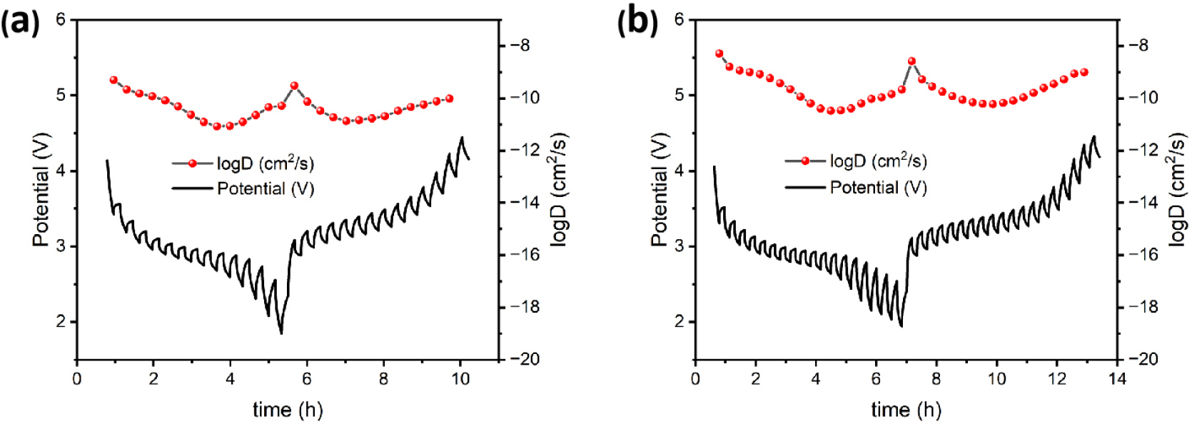
GITT was utilized to compare the sodium ion diffusion coefficients of pristine NFPS and cobalt-doped NFPS-Co0.08. The following equation was used [Eq. (1)].46)
where mB, VM, and MB denote the mass, molar volume, and molecular weight of the cathode material, respectively; τ represents the duration of the charge or discharge process; ΔEs is the quasi-equilibrium potential, and ΔEτ is the change in cell voltage; S is the surface area of the active material. The GITT analysis and the corresponding GCD curves in Fig. 12 demonstrate the diffusion capabilities of Na+. Over the course of charging and discharging, NFPS-Co0.08 exhibited diffusion coefficients ranging from 3.27 × 10⁻¹¹ cm2 s-1 to 5.11 × 10⁻⁹ cm2 s-1. In contrast, the diffusion capabilities of NFPS are inferior to those of NFPS-Co0.08, thus reinforcing the rate performance enhancements brought about by Co2+ doping.
4. Conclusion
The compounds Na1-2xCoxFe2PO4(SO4)2 (x = 0, 0.06, 0.08, 0.10) were synthesized via a facile synthetic method. Systematic characterization of the four samples was conducted using XRD, XPS, SEM, BET, CV and GITT, with particular emphasis on the diffusion kinetics of Na+. XRD Rietveld refinement indicated an increase in particle volume in the doped samples, consequently broadening the Na+ diffusion channels and partially explaining the enhanced sodium-ion kinetic performance. The XPS results revealed that cobalt doping generated a higher concentration of oxygen vacancies compared with the undoped samples. SEM analysis revealed a more uniform void and pore distribution in the modified samples. BET measurements showed that doping with Co2+ resulted in a increased specific surface area for NFPS-Co0.08 compared to NFPS, thereby shortening the sodium-ion diffusion path and promoting ion dynamics. Incorporating Co2+ into the samples notably improved their performance during galvanostatic charge-discharge tests. Notably, NFPS-Co0.08 exhibited superior performance, achieving a discharge potential platform of 78.3 mA h g-1 at a current density of 25 mA g-1 and accommodating more sodium ions. Single-scan and multi-rate CV analyses, combined with GITT, confirmed that Co2+ doping significantly enhances the structural stability and sodium-ion diffusion kinetics. We believe that the results are useful to clarify the phase and structure characteristics of polyanionic materials to promote their application for large-scale energy storage. This will facilitate the development of more cost-effective sodium-ion batteries.
