

1. Introduction
Lithium-ion batteries (LIBs) are pivotal energy storage systems (ESSs) utilized in a wide range of applications, including electric vehicles (EVs), grid-scale ESSs, and portable electronic devices. Among the key components of an LIB, the cathode material plays a crucial role in determining the energy density, power capability, cycle life, and safety of LIBs. Since the proposal of the layered LiCoO2 cathode material by John B. Goodenough in the 1980s, which exhibits a high operating potential (3.8-4.0 V vs. Li+/Li) and excellent structural stability, cathode materials have been extensively studied. However, toxicity and supply chain vulnerabilities of cobalt have prompted efforts to reduce its content in cathode materials. Consequently, research has focused on increasing the proportions of nickel and manganese. Specifically, nickel offers higher energy density, while manganese enhances thermal stability.1,2)
Meanwhile, high-nickel (Ni content ≥ 90 %) cathode materials experience severe volume changes during prolonged cycling, which often leads to structural collapse and rapid capacity fading. These materials also suffer from intrinsic structural imperfection such as a high degree of cation mixing (Li+/Ni2+ antisite mixing) and formation of irreversible phase. To address these challenges, strategies such as elemental doping and surface coating have been investigated to improve structural stability.3,4,5,6) Recently, multi-element doping has attracted increasing attention because this strategy provides the synergistic effects among multiple elements to overcome the limitations of conventional ternary or quaternary compositions (LiNixCoyMn1-x-yO2, LiNixCoyAl1-x-yO2, LiNixCoyMnzAl1-x-y-zO2, etc.)
Traditionally, dopants were introduced during the high-temperature calcination process. Recently, research has emerged on the high-entropy cathode materials that were synthesized by incorporating five or more elements during the coprecipitation of the precursor. These studies demonstrate that the thermodynamic tendency to maximize entropy enables the coprecipitation of multiple, often immiscible, elements into a single-phase precursor. Among various synthesis techniques, hydroxide coprecipitation is considered the most economical, efficient, and scalable method. The use of a continuously stirred tank reactor (CSTR) is advantageous because it ensures consistency and uniformity in precursor properties, including secondary particle morphology, primary particle arrangement, and particle size distribution, all of which are critical for final cathode performance.7,8,9,10,11) Furthermore, CSTR-based synthesis enhances product quality and reduces production costs by providing compositional and morphological homogeneity.12)
The final structure and morphology of precursors are affected by various parameters including stirring speed, reaction temperature, feeding rate, pH, and metal cation and ammonia concentration.12,13,14,15) Specifically, ammonia acts as a chelating agent, forming complexes with transition metal cations (TM2+). This complexation allows for the gradual release of metal ions, which subsequently react with hydroxyl ions to form precipitates with a uniform composition.
This study focuses on the synthesis of nine-element precursors with a target composition of Ni0.8Co0.08Mn0.03Sn0.02Mg0.02Zn0.02Ca0.01Fe0.01Al0.01(OH)2 via coprecipitation under different ammonia concentrations. We investigate the effects of ammonia concentration on precursor growth and the subsequent impact on the electrochemical properties of the calcined active materials.
2. Experimental Procedure
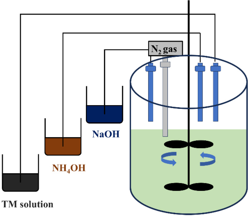
Precursors were synthesized in a 5 L CSTR, as depicted in Fig. 1. A 2 M aqueous metal sulfate solution, a 4 M of NaOH solution (Samchun Chemical, Korea), and a 14.8 M of NH4OH solution (Samchun Chemical, Korea, 28.0-30.0 %) were used as reagents. The metal sulfate solution was prepared by dissolving NiSO4・6H2O (98.5-102.0 %), CoSO4・7H2O (98.0 %), MnSO4・H2O (98.0 %), SnSO4 (98.0 %), MgSO4・7H2O (99.0 %), ZnSO4・7H2O (99.0 %), CaSO4・2H2O (98.0 %), FeSO4・7H2O (98.0-102.0 %), and Al2(SO4)3・14-18H2O (51.0-57.5 %) (all from Samchun Chemical, Korea) in deionized (DI) water to achieve a target metal molar ratio of Ni : Co : Mn : Sn : Mg : Zn : Ca : Fe : Al = 0.8 : 0.08 : 0.03 : 0.02 : 0.02 : 0.02 : 0.01 : 0.01 : 0.01.
Initially, the reactor was filled with an aqueous ammonia solution at 1.5 M or 3.0 M concentration and purged with nitrogen. The solution was heated to 55 °C and then coprecipitation reaction was initiated. The metal sulfate solution was fed into the reactor at a rate of 0.16 mol/h, while the NH4OH solution was added at a constant rate to maintain the desired molarity. The addition of the NaOH solution was regulated to maintain a constant pH of 11.5. The mixture was stirred at 1,100 rpm for 10 h to promote the formation of spherical precursors. The resulting precipitates were washed several times with DI water via vacuum filtration to remove residual Na+ and SO42- ions and then dried in an oven at 80 °C for 12 h.
The dried precursor was intimately mixed with LiOH・H2O (Samchun Chemical, Korea) in a 1 : 1.03 molar ratio using a mortar and pestle. The mixture underwent a two-step calcination process under an oxygen atmosphere, pre-heating at 400 °C for 5 h followed by the calcination at 750 °C for 15 h to obtain the active material. Hereafter, the precursors and active materials are denoted by the ammonia concentration used during synthesis (e.g., 1.5 M and 3.0 M).
The crystal structures of the precursors and cathode materials were analyzed by powder X-ray diffraction (XRD; D2 PHASER, Bruker) over a 2θ range of 10°-70° at a scan rate of 0.008 °/s. The elemental compositions of the precursors were determined by inductively coupled plasma-optical emission spectrometry (ICP-OES; OPTIMA 7300 DV, Perkin-Elmer, USA) following microwave digestion in aqua regia (UltraWAVE, Milestone). Particle morphologies and elemental distributions were investigated using a field-emission scanning electron microscope (FE-SEM; CLARA, TESCAN) equipped with energy-dispersive X-ray spectroscopy (EDS).
For the evaluation of electrochemical properties, cathode slurries were prepared by blending the active material, a conductive agent (Denka black), and a binder (polyvinylidene difluoride (PVDF)) in a 90 : 5 : 5 weight ratio with N-methyl-2-pyrrolidone (NMP) as the solvent. The slurry was uniformly cast onto aluminum foil using a doctor blade and dried in a vacuum oven at 120 °C for 12 h. The dried electrodes were calendared to increase electrode density. The mass loading of active material was measured to be ~6.64 mg/cm2. CR2032-type coin cells were assembled in an argon-filled glovebox using the prepared cathodes as the working electrode, lithium metal as the counter electrode, a polypropylene membrane (Celgard 2320) as the separator, and 1 M LiPF6 in a 1 : 1 : 1 (v/v/v) mixture of ethylene carbonate (EC), dimethyl carbonate (DMC), and ethyl methyl carbonate (EMC) as the electrolyte. The electrochemical performance was evaluated over a voltage range of 2.7-4.3 V (vs. Li+/Li) using a battery cycler (MIHW-200-160CH, Neware) in a temperature-controlled chamber.
3. Results and Discussion
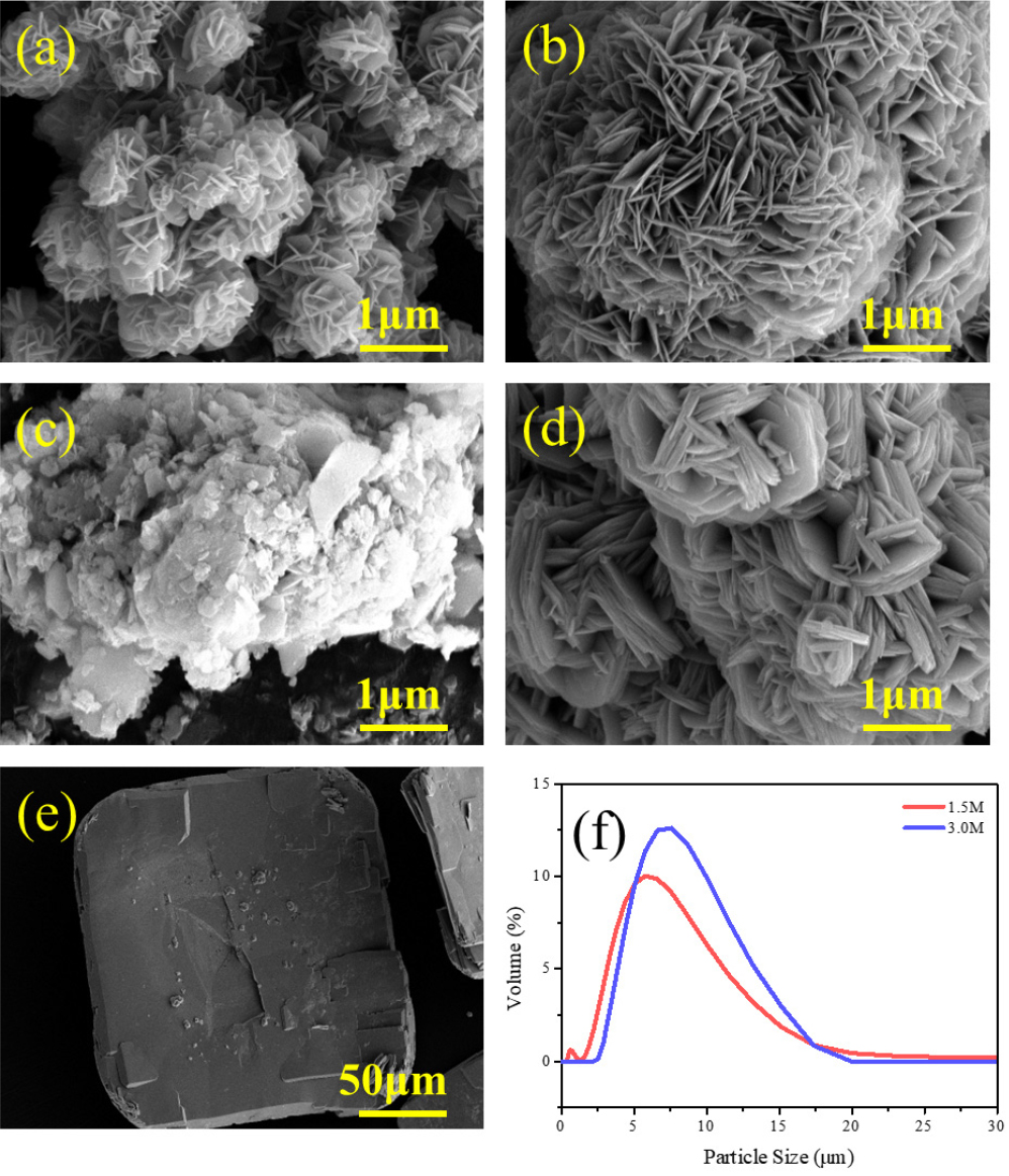
The precursors synthesized via coprecipitation under 1.5 M and 3.0 M ammonia concentrations were grayish-green. Fig. 2. displays the SEM images of both precursors with different reaction times and the particle size analysis (PSA) of the final products. After 1 h of reaction [Fig. 2(a) and Fig. 2(b)], both precursors consisted of randomly oriented, plate-like primary particles. Both precursors exhibited the spherical morphologies after 10 h reaction; however, the primary particles of the 3.0 M precursor showed a greater degree of stacking and preferential orientation compared to the 1.5 M precursor [Fig. 2(c) and Fig. 2(d)]. At higher ammonia concentration, the primary particles appear to preferentially stack along the c-axis rather than grow along the ab-plane, resulting in thicker primary particles for the 3.0 M precursor. Interestingly, a separate impurity phase [Fig. 2(e)] was observed during the filtration of the 1.5 M precursor. In contrast, the higher ammonia concentration (3.0 M) offered a growth-dominated environment, resulting in the formation of precursors with more uniform secondary particles. As shown in the PSA [Fig. 2(f)], a lower ammonia concentration (1.5 M) appeared to lead to the favorable nucleation over growth, resulting in a bimodal particle size distribution. Fig. 2. SEM images of 1.5 M precursors after (a) 1 h and (b) 10 h, and 3.0 M precursors after (c) 1 h and (d) 10 h. (e) Impurity of the 1.5M precursor and (f) PSA results.
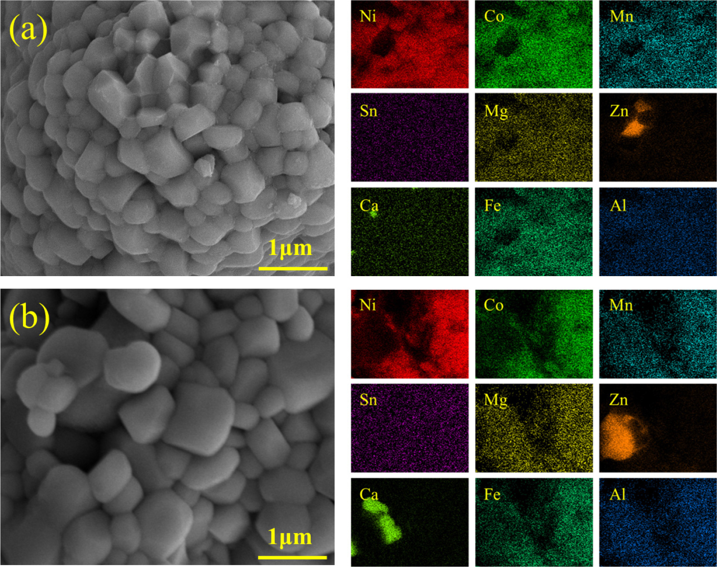
The morphology and elemental distribution of the final cathode active materials, calcined under identical conditions, were examined using SEM and EDS (Fig. 3). The SEM images show that the 3.0 M active material is composed of larger primary particles than its 1.5 M counterpart, indicating that morphology of the final active material is inherited by that of the precursor. This result implies that the cathode morphology can be further tuned by controlling the ammonia concentration during precursor synthesis. EDS mapping revealed a uniform distribution for most elements; however, Zn and Ca showed a tendency to aggregate into specific regions. Considering their relatively large ionic radii (Ca2+: 100 pm; Zn2+: 74 pm), compared to Ni2+ (69 pm), Co3+ (65 pm), and Mn4+ (53 pm), these ions have limited solubility in the layered α-NaFeO2 (R-3m) structure. Consequently, they are prone to segregation rather than uniform incorporation into the host lattice.
The crystal structures of the precursors and active materials were analyzed using XRD. As shown in Fig. 4(a), XRD patterns confirmed that all precursors crystallized in the β-Ni(OH)2 structure (space group P3m1). The impurity phase in the precursor was identified by SnO as presented in the XRD pattern of the 1.5 M precursor [Fig. 4(a)]. This indicates that a 1.5 M ammonia concentration was not enough to achieve single-phase synthesis during coprecipitation. After calcination, both active materials crystallized into the desired α-NaFeO2-type layered structure with space group R-3m [Fig. 4(b)]. As summarized in Table 1, the I(003)/I(104), intensity ratio of (003) and (104) peaks, which is used as an simple indicator of cation mixing,16) was higher for the 3.0 M cathode, suggesting a more well-crystalized layered structure. Furthermore, the clear splitting of the (108) and (110) peaks for the 3.0 M cathode indicates its superior crystallinity compared to the 1.5 M cathode.17) These structural characteristics suggest that the 3.0 M cathode reveals a more stable layered framework.
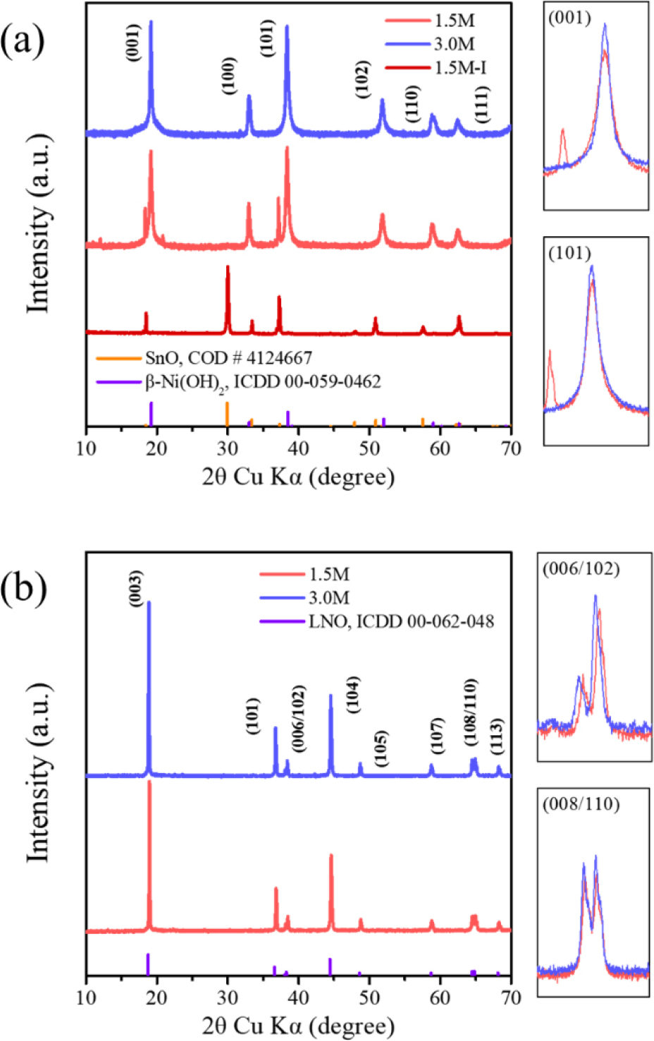
Table 1.
XRD peak ratios.
| Samples |
I(100)/ I(001) |
I(101)/ I(001) |
I(110)/ I(001) |
I(003)/ I(004) |
(I(006)+I(102))/ I(101) |
| 1.5 M | 0.60 | 1.03 | 0.44 | 1.96 | 0.56 |
| 3.0 M | 0.48 | 0.93 | 0.36 | 2.14 | 0.48 |
The electrochemical performances of the 1.5 M and 3.0 M cathode materials were evaluated. As shown in Fig. 5(a), cells underwent two formation cycles at 0.1 C (1 C was assumed to be 20 mA/g), followed by rate capability and cycling stability tests. Both samples delivered a similar initial discharge capacity of ~180 mAh/ g at 0.1 C. At a rate of 1 C, the initial capacities were also comparable. 164.87 mAh/g and 163.35 mAh/g were achieved for the 3.0 M and the 1.5 M cathode materials, respectively. However, their cycling stability differed significantly. After 50 cycles at 1 C, the 3.0 M cathode retained 172.58 mAh/g (95.6 % capacity retention compared to that of the first cycle), while the 1.5 M cathode showed the capacity decrease to 155.38 mAh/g (86.7 % capacity retention). After 100 cycles, the 3.0 M cathode maintained a capacity of 164.22 mAh/g (91.0 % capacity retention), whereas the capacity of the 1.5 M cathode was decreased to 123.97 mAh/g (69.2 % capacity retention).
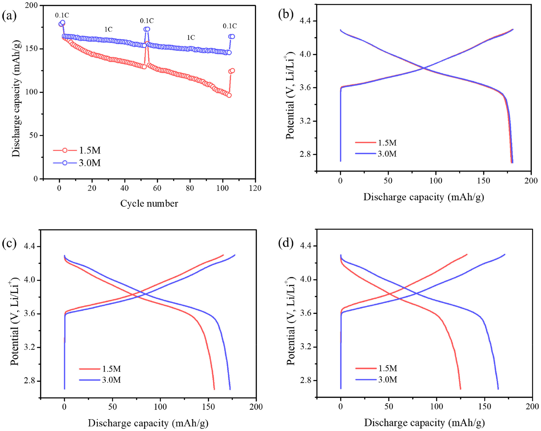
SEM observations reveal that the primary particles of the 3.0 M active material are larger than those of the 1.5 M sample, which reduce the surface area and mitigate side reactions, thereby improving chemical stability. In addition, the accelerated capacity fading of the 1.5 M can be attributed to its higher degree of cation mixing and lower crystallinity as indicated by the XRD analysis, which lead to more structural instability during repeated cycling.18,19,20)Fig. 5(b-d) display the capacity vs. voltage profiles at the representative cycles, indicating the more pronounced capacity decay of the 1.5 M cathode.
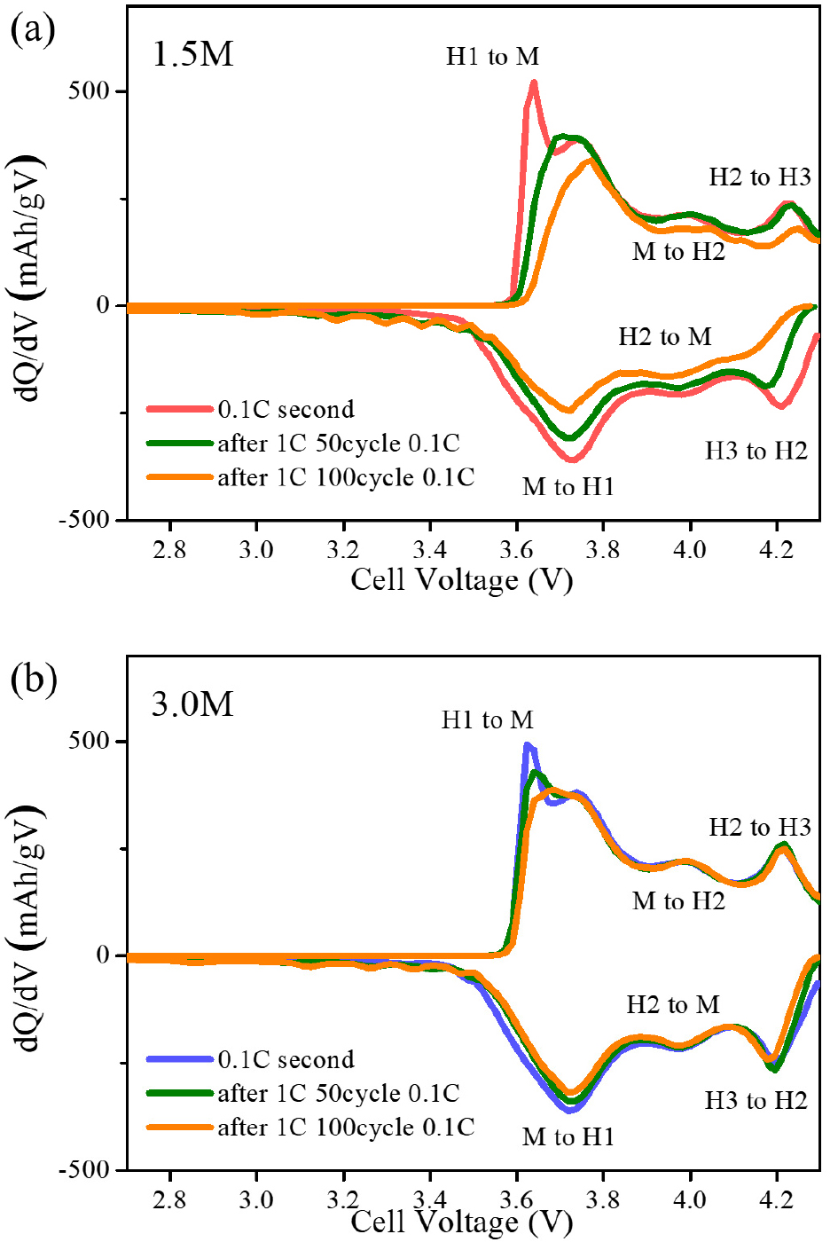
This behavior is further corroborated by the differential capacity (dQ/dV) profiles (Fig. 6). The three distinct redox peak pairs are observed at approximately 3.84/3.70 V, 4.03/3.96 V, and 4.22/4.10 V corresponding to the phase transitions from hexagonal (H1) to monoclinic (M) phases, M to hexagonal (H2) phases, and H2 to hexagonal (H3) phases, respectively.21) For the 1.5 M cathode, the oxidation/reduction peaks associated with the H2-H3 transition progressively diminish in intensity and shift upon cycling, being accounted for the increase of polarization followed by a loss of structural reversibility. This irreversible behavior is mainly ascribed to the anisotropic volume changes during the H2-H3 transition,22) which induce internal stress and microcrack formation, thereby accelerating capacity and cycle degradation.
4. Conclusion
In this study, high-nickel, nine-component hydroxide precursors with a target composition of Ni0.8Co0.08Mn0.03Sn0.02Mg0.02Zn0.02Ca0.01Fe0.01Al0.01(OH)2 were synthesized via a coprecipitation method under different ammonia concentrations. Although the studied conditions were not fully optimized to achieve the target stoichiometry, distinct morphological differences in the precursors were observed as a function of ammonia concentration during coprecipitation reaction. Precursors synthesized at a low ammonia concentration (1.5 M) consisted of randomly oriented primary particles with a secondary SnO phase. In contrast, a higher ammonia concentration (3.0 M) promoted the formation of thicker, more stacked primary particles without any impurity phases. The precursor morphologies largely affected the final cathode materials after calcination. The cathode material derived from the 3.0 M ammonia precursor exhibited a lower degree of cation mixing and superior crystallinity. Consequently, the electrochemical tests revealed a clear contrast in performance. The 1.5 M cathode exhibited severe capacity fading, attributed to its higher cation mixing and poorer structural stability. In contrast, the 3.0 M cathode demonstrated excellent long-term cycling stability, delivering an initial discharge capacity of 180.50 mAh/g at 0.1 C and retaining 164.22 mAh/g after 100 cycles at 1 C, corresponding to 91 % capacity retention. This work highlights the influence of ammonia concentration on the structural and electrochemical properties of multi-component, high-nickel cathode materials.
