

1. Introduction
2. Experimental Procedure
3. Results and Discussion
3.1. Insulation breakdown voltage with ambient temperature change
3.2. Temperature change of insulating oil according to ambient temperature change
4. Conclusion
1. Introduction
The importance of liquid dielectrics, such as insulating oil used in electrical equipment, is significant due to the increasing demand for electricity, which has led to the use of large-scale equipment and ultra-high voltage transmission systems requiring high voltage insulation.1) Recently, outstanding materials with excellent insulating properties have been developed and are being used in various electrical devices. With the trend toward higher transmission voltages, insulating oil plays a crucial role in electrical equipment insulation.2)
Industries demand high reliability and quality of power energy, simplified operation and maintenance of equipment, and assurance of reliability and stability in power system operations.3) Liquid insulators used in immersed equipment generally need to have excellent cooling properties, high flash points, and chemical stability with strong resistance to internal corrosion.4) With continuous economic development leading to a rapid increase in energy consumption, the importance of insulation performance in large-capacity, ultra-high voltage immersed electrical equipment has risen, necessitating effective management and operation strategies for such equipment. Typically, the insulating oils used are of the KSC 2301 standard, Grade 1, Class 2, which have high thermal expansion coefficients and insulation strength, and are relatively inexpensive compared to other insulating oils, making them economically advantageous.5,6)
In the past, research on insulation breakdown through electrode material studies was conducted in the 1970s, while in the 2000s, the impact of voltage magnitude and polarity on flashover characteristics using spherical electrode shapes was investigated.6) Additionally, numerous studies have been conducted on the insulating characteristics of liquid dielectrics and transformer insulating oils, including research on changes in breakdown voltage due to various electrode arrangements and distances, as well as the behavior of bubbles in cryogenic liquids. Research has also focused on assessing the suitability of insulating oil’s insulation strength and its characteristics under conditions unaffected by decomposition products in the oil.6,7,8,9,10,11,12,13,14)
Refined hydrocarbons derived from crude oil were primarily used in the form of paraffinic mineral oils in the 1880s. However, since the 1920s, naphthenic mineral oils, distilled and refined from crude oil with higher stability, have been predominantly used.15)
Previous studies mainly focused on the types of insulating oils, electrode types and distances, and field intensities under varying conditions. Therefore, this paper investigates whether the electrical properties of transformers change with temperature variations, considering Korea’s four distinct seasons. The study also examines the impact of ambient temperature changes on the insulation performance of insulating oils. Insulation breakdown experiments were conducted with varying electrode shapes and distances, and ambient temperatures set at 0, 10, 20 and 30 °C to analyze the electrical properties of insulating oils through breakdown experiments.
2. Experimental Procedure
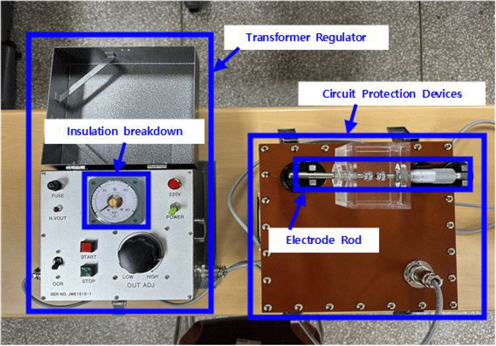
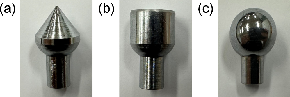
The central experimental unit is an insulation oil breaking voltage tester used in the insulation breaking experiment. The main unit consists of a transformer voltage regulator, a circuit protection device and a voltmeter. In this study, the temperature changes before and after dielectric breakdown were measured (Fig. 1), and the infrared thermometer of the SK-8700II model was used. A total of 6 electrode type combinations were shown using 3 electrode types (Fig. 2).
The insulation breakdown experiment was conducted at different ambient temperatures: 0, 10, 20 and 30 °C, with experiments performed at 10 °C intervals. Before starting the experiments, the laboratory temperature was measured using a thermometer to ensure it matched the experimental conditions. To simulate the actual external environment, insulation oil was placed in an oil cup at each of these temperatures, and a timer was set for 1 hour to stabilize the temperature.
The electrode gaps were varied in four steps: 1.5, 2.0, 2.5 and 3.0 mm, with each step being 0.5 mm apart. The electrode shapes used were sphere, plate, and needle electrodes, resulting in a total of six electrode configurations: sphere-sphere, plate-plate, sphere-plate, needle-needle, sphere-needle, needle-plate.
After setting up the insulation oil breaking tester, oil cup, insulation oil and other experimental equipment, the stability of the insulation oil was checked, and the temperature of the insulation oil was measured using an infrared thermometer. Starting the experiment, the system was monitored until the insulation failure occurred. The breakdown voltage and temperature of the insulation oil were recorded at the moment of the insulation failure. The above procedure was repeated for each of the six electrode configurations: sphere-sphere, plate-plate, sphere-plate, needle-needle, sphere-needle, needle-plate, with electrode spacing set at 1.5, 2.0, 2.5 and 3.0 mm. Each spacing setting was tested six times.
In addition, oil insulation temperatures were measured and recorded before and after each experiment to consider ambient temperature changes.
3. Results and Discussion
3.1. Insulation breakdown voltage with ambient temperature change
The average insulation breakdown voltage at an ambient temperature of 0 °C is shown in Fig. 3(a). From these measurements, it was observed that the insulation breakdown voltage increases with the electrode gap distance. The breakdown voltage was highest in the following order of electrode shapes: sphere-sphere, plate-plate, sphere-plate, needle-needle, sphere-needle, needle-plate. Additionally, at an ambient temperature of 0 °C, the insulation breakdown voltage was found to be unstable when using plate-plate and sphere-plate electrode shapes.
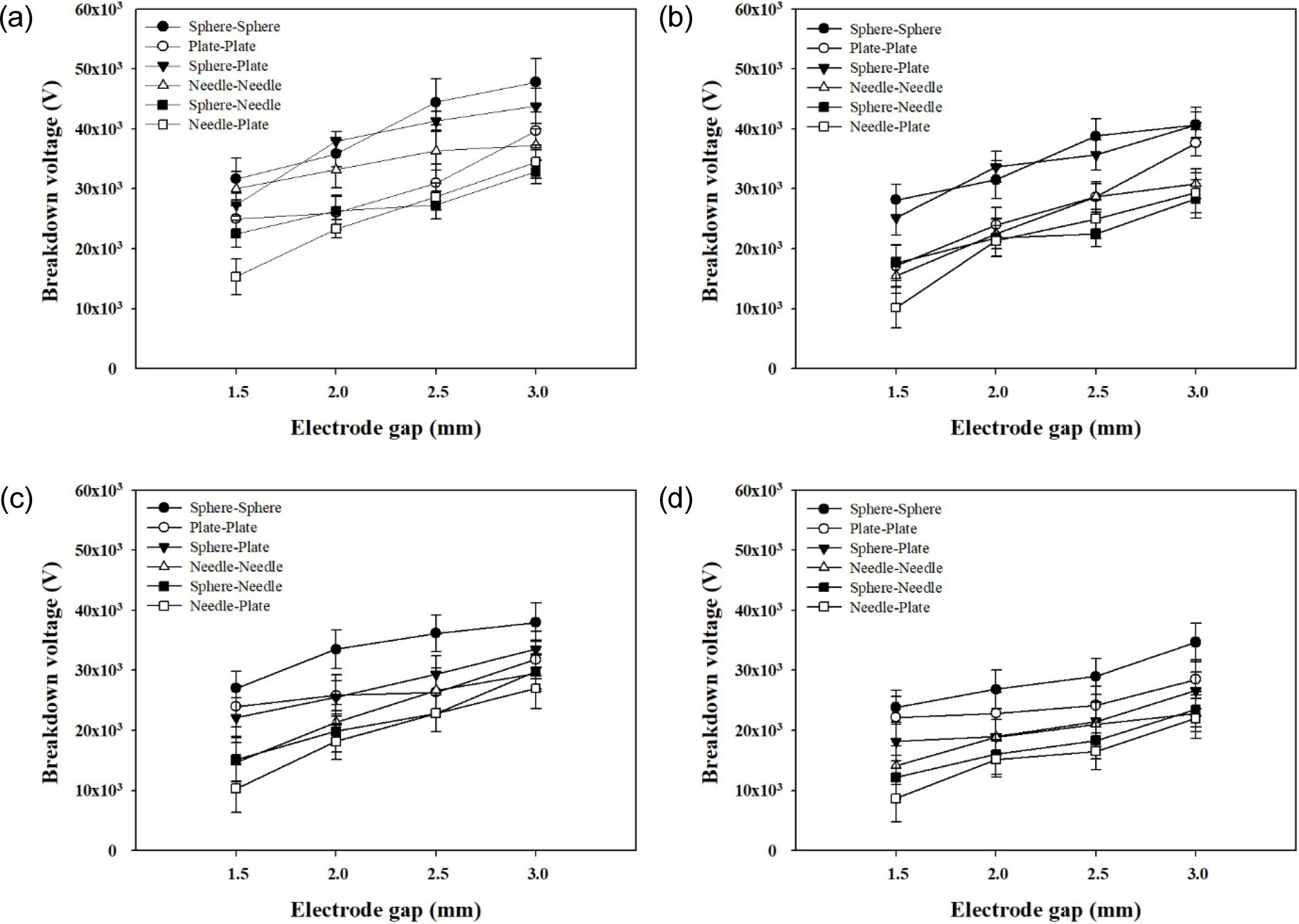
Fig. 3(b) also shows the average breakdown voltage at an ambient temperature of 10 °C. From these measurements, it was observed that the insulation breakdown voltage increases with the electrode gap distance. The breakdown voltage was highest in the following order of electrode shapes: sphere-sphere, plate-plate, sphere-plate, needle-needle, sphere-needle, needle-plate. It was also noted that at an electrode gap of 2.0 mm, the breakdown voltage for the sphere-sphere electrode configuration dropped sharply, suggesting a deterioration in insulation performance.
When the average breakdown voltage at an ambient temperature of 20 °C was investigated, it was observed that the breakdown voltage increased with the electrode gap distance. And the breakdown voltage was highest in the order of electrode shape [Fig. 3(c)]. And the average insulation breakdown voltage at an ambient temperature of 30 °C is shown in Fig. 3(d). From these measurements, it was observed that the insulation breakdown voltage increases with the electrode gap distance. The breakdown voltage was highest in the following order of electrode shapes: sphere-sphere, plate-plate, sphere-plate, needle-needle, sphere-needle, needle-plate.
3.2. Temperature change of insulating oil according to ambient temperature change
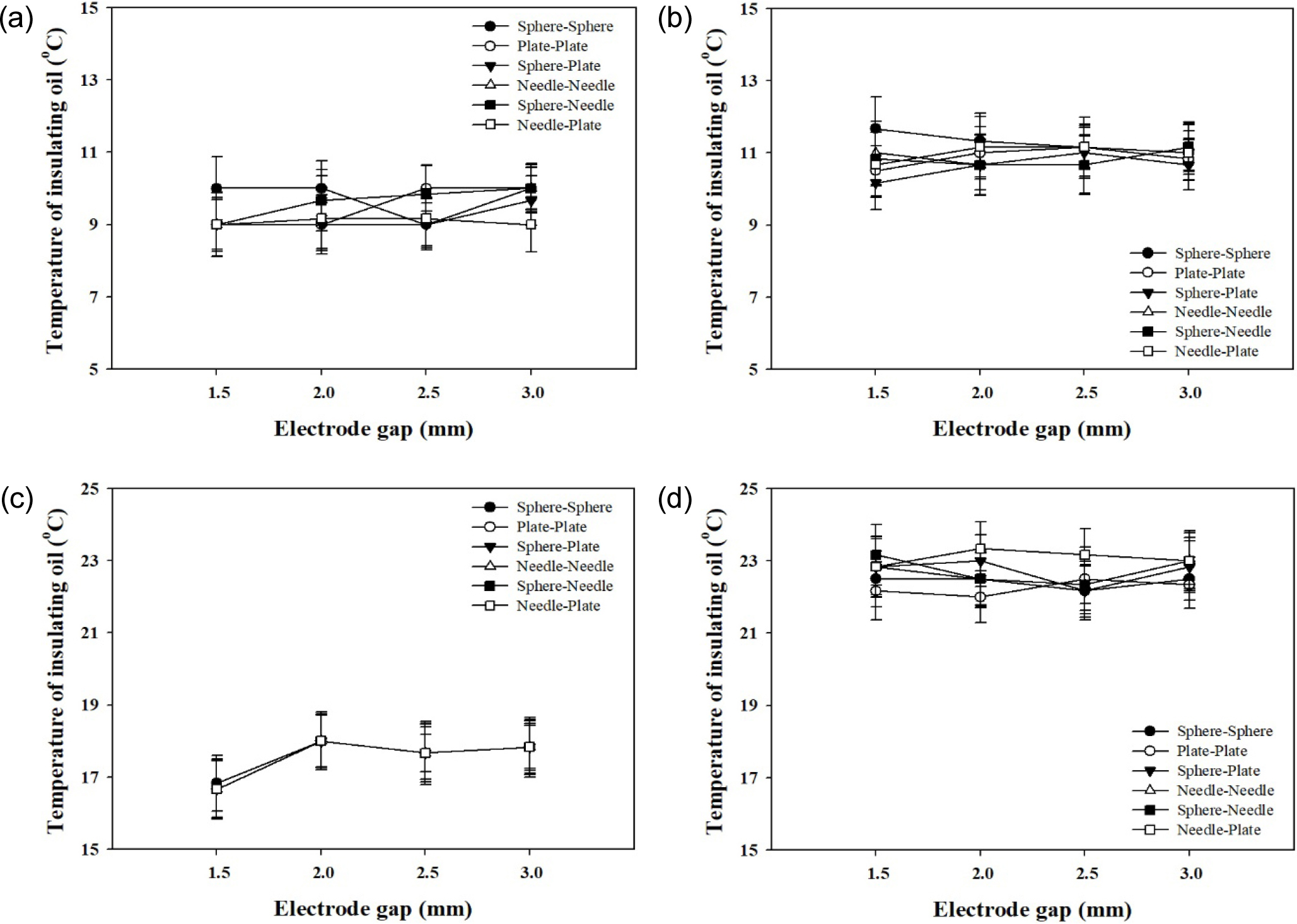
As a result of investigating the temperature change of the insulating oil according to the change in the ambient temperature, it was found that the breakdown voltage increased according to the electrode spacing distance (Fig. 4). The breakdown voltage showed differences according to the electrode shape, and the order was as follows: sphere-sphere, plate-plate, sphere-plate, needle-needle, sphere-needle, needle-plate. However, at each ambient temperature of 10, 20 and 30 °C, the insulating oil temperature at the time of breakdown did not change significantly according to the electrode spacing or electrode configuration (Fig. 4).
4. Conclusion
This paper investigates how transformer electrical characteristics―specifically the insulation performance of insulating oil―change with electrode type, electrode gap, and ambient temperature. Experiments used three electrode shapes (spherical, plate, and needle) arranged into six configurations (sphere-sphere, plate-plate, sphere-plate, needle-needle, sphere-needle, needle-plate). Breakdown tests were performed at four gap distances (1.5, 2.0, 2.5 and 3.0 mm) and four ambient oil temperatures (0, 10, 20 and 30 °C) to analyze the influence of electrode geometry and temperature on breakdown behavior.
(1) The insulation breakdown voltage is higher when the ambient temperature is lower.
(2) The breakdown voltage varies with electrode type in the following order: spherical-spherical, spherical-plate, plate-plate, needle-needle, spherical-needle, needle-plate.
(3) The breakdown voltage increases as the electrode gap increases.
(4) Changes in ambient temperature do not significantly affect the temperature of the insulation oil at breakdown.
(5) Across 0~30 °C and electrode gaps of 1.5~3.0 mm, the breakdown voltage increased as ambient temperature decreased (e.g., 15.3 → 8.7 kV at 1.5 mm and 47.8 → 34.7 kV at 3.0 mm), and it also increased with a larger electrode gap, indicating improved insulation performance. This trend is consistent with Koppelmann’s theory: lower temperatures reduce molecular motion in liquid insulating oil, suppressing structural changes or defect formation and thereby increasing breakdown voltage.
(6) At 10 °C (the condition associated with the highest breakdown voltages), the breakdown voltage varied by electrode configuration. From highest to lowest, the results were: sphere-sphere (31.7~47.8 kV), sphere-plate (27.3~43.8 kV), plate-plate (25.0~39.7 kV), needle-needle (30.0~37.3 kV), sphere-needle (22.5~32.8 kV), and needle-plate (15.3~34.5 kV). This indicates that electrode geometry alters the electric-field distribution, which in turn influences the breakdown voltage.
(7) The average insulation-oil temperature at breakdown was about 9.0~10.0 °C at an ambient temperature of 0 °C, 10.2~11.7 °C at 10 °C, 16.7~18.0 °C at 20 °C, and 22.2~23.3 °C at 30 °C. This indicates that the breakdown oil temperature follows ambient temperature, whereas variations in electrode gap and electrode type have little influence on the oil temperature at breakdown. These results confirm that the insulation performance varies with breakdown voltage due to changes in electrode type and temperature. Lower ambient temperatures lead to higher breakdown voltages, and increased electrode gaps also result in higher breakdown voltages, indicating improved insulation performance. Variations in electric field strength due to different electrode configurations result in differences in breakdown voltage and insulation performance. This research can serve as a reference for maintaining the insulation performance of liquid insulation oil in transformers, considering local environmental characteristics.
