

1. Introduction
It is widely recognized that fossil fuels are causing serious environmental problems, so hydrogen is considered one of the ideal fuels for replacing them.1-3) With fossil fuels becoming expensive, it is vital to harness renewable energy sources further. Due to the urgency of reducing greenhouse gas emissions without compromising modern living, renewable and clean energy sources have attracted unprecedented interest.4,5) It is important, however, to note that the energy supply from such renewable sources is inconsistent as a result of seasonal, daily, and regional fluctuations. By considering all points mentioned before using electrochemical water splitting to produce fossilfree, renewable, clean hydrogen for energy generation, electrochemical water splitting can contribute to the development of a sustainable energy system.6,7) Water splitting with electrochemical means offers hydrogen production, but this is limited because there is a limitation on the reactions, particularly at the anode surface where oxygen evolution reaction (OER) takes place. Pt, Ir, and Ru-based electrocatalysts are state of art catalyst materials. But they cannot be used in large-scale applications owing to their excessive costs, and scarcity. Therefore, the fabrication of durable, and inexpensive electrocatalysts or materials is in demand.8,9)
Due to the metalloid nature of transition metal phosphate (TMP) and the formation of metal-oxo/hydroxo species in situ during OER, transition metal phosphates have received extensive attention as electrocatalysts.10-12) In addition, external atoms can enhance the functioning of the TMP catalyst by altering its atomic and electronic structure, and surface morphology creating additional active M-OH centers, and modifying the adsorption free energy.13,14)
Considering the above points, here in this article, we have reported the simple and cost-effective synthesis of cobalt phosphate hydrate (CP) on nickel foam by successive ionic layered adsorption and reaction (SILAR) method followed by sulfurization in a chemical bath. The CP has shown sheet-like morphology and CPS samples possess smaller granules on the sheets of CP that have been observed. Both materials exhibited remarkable performance for OER with high stability.
2. Experimental Method
2.1. Synthesis of cobalt phosphate hydrate
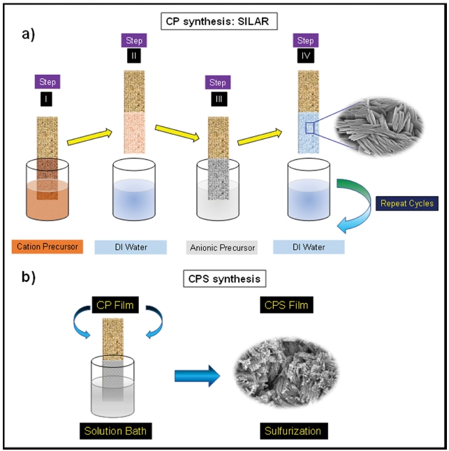
In this synthesis, we have used a simple and costeffective approach for making electrocatalyst. The SILAR is well known facile and most used technique. Firstly, Co(NO3)2.6H2O was dissolved in 60 mL of water having 0.05 molarity and the same is for the Na2HPO4 source. Both solutions were stirred vigorously to make them homogeneous and marked as Sol A [(Co(NO3)2).6H2O] and Sol B (Na2HPO4) respectively. Then beakers were placed in the row like Sol A, DIW, Sol B, and DIW. The process consists of adsorption (Sol A), rinsing (DIW), and reaction (Sol B), followed by rising (DIW) for 20, 30, 20, and 30 s, respectively. The whole process was repeated for 100 cycles and was followed by a drying process at 70 °C for 3 h.
The prepared films were kept in a 0.1 M solution of Na2S and kept at a temperature of 70 °C for 1 h. The whole process is diagrammatically represented in Fig. 1. Finally, after completion of the reaction thin film was kept for drying at 70 °C for 30 min, and then thin films were employed for further characterizations.
3. Results and Discussion
3.1. Structural and morphological characterization
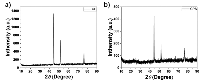
To identify structural parameters of prepared samples the X-ray diffraction (XRD) study was performed on the Rigaku Dmax/Ultima IV diffractometer with monochromatized Cu Kα radiation [Cu 2KW (Max. 60 kV 55 mA)]. The diffraction pattern was then analyzed, and it is presented in Fig. 2. The XRD pattern reveals an amorphous crystal structure for both CP and CPS. The intense diffraction peaks at 44.8°, 52.2°, and 76.8° are attributed to nickel foam (NF). The absence of any other peak confirms the purity of the synthesized material.
The morphological study of synthesized thin films is shown in Fig. 3. The morphology of the deposited samples was examined by field-emission scanning electron microscopes (FE-SEM, FEI Nova Nano SEM 450). The study revealed that as-deposited CP materials forms nanosheet-like structures along with fine edges which can be very clear by looking at the images provided in Fig. 3(a) ~ (c). The figures depict the well-aligned vertical petals-like structure over the whole area of the film. The nanosheets offered high surface area along with huge active sites for catalysis. Moreover, Fig. 3(d) ~ (f) are the FE-SEM images of CPS thin films after the sulphuration, showing nanosheets grown on CP sheets. These ununiform grown nanosheets decorated into the surface area become rich in electrochemical active sites. After the sulfurization, the particles of sulfur are seen to be uniformly distributed over the entire selected area, as shown in Fig. 3(f). The sulfurization of thin films significantly alters the surface texture.
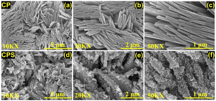
Fig. 3
(a-c) are the FE-SEM images of CP at different magnifications and (d-f) are FE-SEM images of CPS at different magnifications.
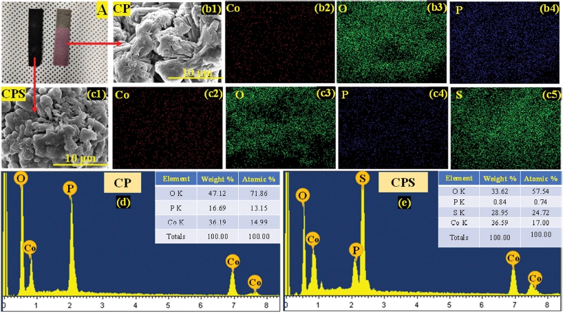
Additionally, the elemental composition of CP and CPS was determined by EDS and its subsequent results are presented in Fig. 4. The elemental mapping of CP thin films as shown in Fig. 4(b1) ~ (b4) confirms Co, P, and O atoms as provided in Fig. 4(e) while after the sulphuration additional ‘S’ atoms present were observed as presented in Fig. 4(f). However, Fig. 4(c1) ~ (c5) demonstrates the elemental mapping of CPS thin films. Through this analysis, it is confirmed that the sulfurization has successfully taken place on the as-prepared CP thin films. There was no evidence of another impurity of atoms have been observed throughout the sample’s areas. The atomic percentage of ‘P’ and ‘O’ decreased tremendously after sulfurization, indicating P has been replaced by ‘S’ atoms. The higher percentage of S indicates that additional O atoms from hydrate molecules were also replaced by ‘S’.
3.2. Electrochemical measurements
All measurements of the electrochemical study were performed on an electrochemical workstation (CHI 760E, CH Instruments Inc., Shanghai) utilizing a standard three-electrode system. Here we used 1 M KOH solution as an alkaline electrolyte, a Pt wire played the role of the counter electrode, a mercury/mercuric oxide electrode (Hg/HgO) was used as a reference electrode, and newly produced CP and CPS nanosheets on nickel foam were directly employed as the working electrode. After the measurements, the potentials converted to a scale of reversible hydrogen electrode (RHS) as per the standard Nernst equation: ERHE = EHg/HgO + (0.098 + 0.059 × pH). The scan rate of 1 mV s-1 was kept during the linear sweep voltammetry (LSV) measurements. The double layer capacitance (Cdl) of the working electrode was determined from cyclic voltammetry (CV) and the measurements were done in the region of 0.0 to 0.20 V vs Hg/HgO by providing scan rates like 10, 20, 40, 60, 80 and 100 mV s-1. The long-term consistent stability was measured using chronopotentiometry at a steady current density of 50 mA cm-2 for 24 h.
3.3. Electrochemical activity towards OER
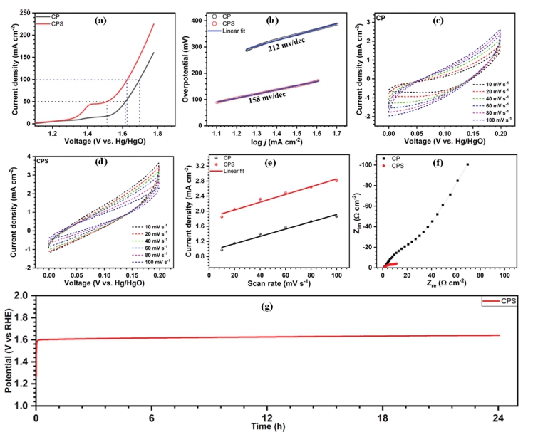
The LSV plots of CP and CPS nanosheets were measured in 1 M KOH electrolyte in a conventional three-electrode arrangement at a scan rate of 1 mV s-1 [Fig. 5(a)]. For the CP electrode 380 mV of overpotential is required to reach a current density of 50 mA cm-2, and on the other hand, after the sulfurization of film, its overpotential reduces to 279 mV, indicating the improvements in the catalytic performance of CP. Fig. 5(b) shows the Tafel slopes of the prepared thin films. It is 158 mV dec-1 for CP and 212 mV dec-1 for CPS. The reason behind this is the quicker rate of transport of electrons for CPS.
Moreover, the electrochemical double-layer capacitance (ECSA) was estimated from Cdl, where Cdl of catalysts was calculated with assessments of the CV curves measured at various scan rates of 10, 20, 40, 60, 80, and 100 mV s-1 as shown in Fig. 5(c) ~ (d). The CPS has high Cdl than CP as shown in Fig. 5(e). The high value of Cdl suggests a higher electrochemically active surface area of CPS thin film and the ECSA for CPS was 255 cm2 compared to 225 cm2 of CP. Furthermore, to understand the better kinetics of OER performance and the reasons behind it, electrochemical impedance spectroscopy (EIS) measurements were performed. The Nyquist plots of CP and CPS are shown in Fig. 5(f). The plots show a low charge transfer resistance for CPS (11.52 Ω cm-2) than that of CP (27.53 Ω cm-2). This result indicates CPS nanosheets on NF facilitate facile electron transport during the OER activity. A chronopotentiometry stability test was carried out to validate the long-term stability of CPS at a current density of 50 mA cm-2 for 24 h. As provided in Fig. 5(f), the CPS showed good water splitting steadiness over 24 h with a mere increase of 22 mV of overpotential.
By deep analysis of the above-presented results, we would like to attribute the enhancement in OER performance of the CPS thin films to several factors associated with it. Firstly, (1) binder-free synthesis of CP results in the vertically aligned growth of sheets. This increased the number of active sites and as a result of it, the final OER performance gets enhanced. Secondly, (2) the Sulfurization process enhances the surface area along with generating more active sites. The elemental analysis study reveals how the S atoms enhancement helps in the improved activity of the CPS thin films. The percentage of O has decreased and on the other hand, the S percentage has risen. Moreover, (3) after sulfurization the morphology of CP changed and nanosheets were observed on CP sheets creating huge active sites. Finally, (4) the sulfurization process also resulted in a reduction in the charge transfer resistance.
4. Conclusion
In the nutshell, we have successfully synthesized cobalt phosphate hydrate nanosheets using a simple and costeffective SILAR method and sulfurized them using a chemical bath of the sulfur source. The XRD confirmed the amorphous nature of CP and CPS thin films. The morphology changes from sheet-like structure to petals grown on sheets. The developed CP and CPS on NF functioned as promising electrodes and showed an excellent OER performance in 1 M KOH electrolyte. The CP electrode and CPS electrode exhibited a low overpotential of 279 and 381 mV to achieve a current density of 50 mA cm-2, respectively. From ESCA and EIS data, excellent catalytical activity after sulfurization due to superior surface area and improved reaction kinetics. The above findings prove that optimum sulfurization CP electrodes are more performing and stable electrodes for the OER in alkaline electrolyte conditions.
