


1. Introduction
Supercapacitors are a category of electrochemical energy storage devices that fairly possess the advantages of both batteries and capacitors. Nowadays, an increasing use of portable electronic devices can be seen in industrial and experimental applications, medical equipments and even daily used cell phones and laptops in which the power storage and power durability are the must-have specifications of all these devices.1-4) Miniaturized power storage devices are used in these applications, among which batteries and supercapacitors are the most important. Fast charge and discharge beside long cycle life and high power density are three notable characteristics which give supercapacitors a great potential to integrate or replace batteries.5-6) To manufacture supercapacitor electrodes, carbon based materials can play an important role.7-8) Graphene, a 2D allotrope of carbon, possesses unique electrical and mechanical properties such as outstanding electrical conductivity, very high theoretical surface area of 2630 m2/g, promising flexibility, and tensile strength of 130 GPa. Therefore, graphene nano-flakes comes in handy to be appropriately utilized in supercapacitors and other energy storage devices.9-11)
It is known that producing graphene derivatives such as graphene oxide(GO) are more convenient than graphene sheets.12) GO could be chemically13) orthermally14) reduced to form graphene. The reduced graphene oxide(rGO) contains numerous defect sites, which could be desirable for electrochemical applications.15) Chen et al. reported that the specific capacitance per weight of graphene nanosheets could reach 30.72 F g−1 at current density of 2 mAcm−2.16) In return graphene composites can significantly improve electrical conductivities, chemical stability and have large surface areas.17) Ma et alreached specific capacitance of 135.36 F g−1 at current density of 1 F g−1 for C60/Graphene Composite supercapacitor.18) However, an attempt at manufacturing a cheap, high-performance supercapacitor for energy saving was performed by yang, which resulted in poly(safranine T)/reduced graphene oxide nanocomposite supercapacitor with a capacitance of 293.2 F g−1 at 20 mV s−1.19) A recently-invented method for reducing graphene oxide by El-Kady et al.20) showed promising advantages over conventional techniques for energy storage applications. In their study, commercially available Light-scribe DVD burner drivers was used to convert GO into rGO. The IR-laser diode of the optical driver irradiates laser beam with a wavelength of 780 nm, which forces oxygen atoms to leave the graphene oxide structure. The resultant reduced graphene oxide, which is called laser-scribed graphene(LSG), is highly defective so that it possesses excellent performance as a supercapacitor.20)
It is possible to pattern desired features on the graphene oxide by controlling the laser beam.21,22) El-Kady and Kaner23) used this technique to fabricate interdigited electrodes, making them possible candidates for flexible energy storage devices. On the other hand, Tian et al.24-27) used LSG to build planar transistors, photo detectors, load speakers and pressure and strain sensorsconcluding that wafer scale direct printing of graphene based devices can be achieved by Lightscribe optical drives. Electrochemical properties of LSG have been investigated by Griffiths et al.28) They used the advantage of highlydeffective surfaces of LSG to fabricate a working electrode with the fastest heterogeneous electron transfer rate even in comparison with commercial edge plane pyrolytic graphite(EPPG) and basal plane pyrolytic graphite(BPPG), and illustrated that the LSG’s fabrication method is inexpensive, scalable and compatible with disposable biosensor format.28) Wen et al. laser treated CNT-graphene oxide mixture29) to fabricate LSG/CNTs hybrid microsupercapacitors. They studied the obtained devices based on the diameters of CNTs, reported that LSG/CNT composite containg smaller CNT dimension exhibited better energy storage performance.
2. Experimental details
The modified Hummers’ method was used to prepareGO, as reported elsewhere.10) Briefly, a mixture of 1 g NaNO3 and 46 ml H2SO4 was provided, then 2 g graphite powder was added to them, and the mixture was cooled to 10 °C using an ice bath. In the next step, 6 g KMnO4 was gradually added to the solution and the reaction temperature was kept below 20 °C. The mixture was then stirred at 35 °C for 2 h. 92 ml of deionized water was added to the resultant solution in order to dilute it, until a dark brown suspension was obtained. Then, the solution was treated by adding 340 ml H2O2 solution. The resultant graphite oxide suspension was washed in two steps:several times by HCl aqueous solution and then by distilled water. Finally, by adding water to the resulting precipitate and 12 h of sonicating, a uniform suspension of GO nanosheets was obtained.
The resultant suspensions were uniformly drop casted on a LightScribe DVD disk and then dried under the air at an ambient temperature. The GO coated DVD disk was placed in a LightScribe DVD drive with a wavelength of 780 nm and a spot size of 20 μm. The reduced solution was peeled off from the DVD disk and was glued to the polyethylene terephthalate(PET) substrate. Silver paste was utilized to attach the prepared electrodes to copper wire and the exposed areas of silver paste to electrolyte were passivated. Fig. 1 illustrates the schematic fabrication process of flexible micro-supercapacitor.
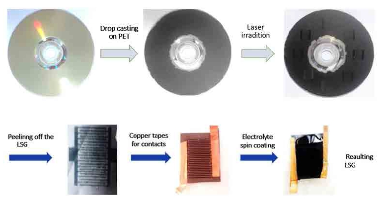
An R129348 Bruker Equinox 55 Fra 106/s spectrometer was used for Raman spectroscopy. The surface of electrodes was observed by FESEM(HITACHI S-4160). Cyclic voltammetry(CV) and galvanostatic charge/discharge( CC) techniques were employed. The electrochemical properties of rGO supercapacitor working electrodes were evaluated using a three-electrode system with platinum rod as a counter electrode, a standard Ag/Ag Clelectrode as a reference electrode and 0.5M KCl solution as an electrolyte. The CV at different scan rates and galvanostatic charge-discharge at various current densities were carried out on a potentio/galvanostat system (RNF 1224). The electrochemical impedance spectroscopy (EIS) measurements were performed in the frequency range from 0.1 Hz to 100 kHz with 5 mV ac amplitude at open circuit potential.
Patterning rGO solution onto interdigitated electrodes was performed using the laser scribing process for the fabrication of flexible micro-supercapacitors. Copper tapes were glued to the patterned electrodes. The composition of gel electrolyte for micro-supercapacitor was KCl and polyether ether ketone(PEEK) polymer. 2 g PEEK was added to 2 mL 0.5 M KCl solution under intense stirring, until a clear solution was obtained. A proper amount of gel electrolyte was droppedon the sample and then spin coated at a rate of 2000 rpm for 30sec to create a uniform gel electrolyte surface. The CV curves and CC profiles of rGO-based micro-supercapacitor were taken by using a two electrode system between cut-off voltages of 0 and 1 V.
3. Results and discussion
Fig. 2 illustrates TEM images of GO for further studying of sheets structure, for this purpose, CM30 Philips TEM apparatus has been utilized, operated at a voltage of 150 kV. Laser scribed graphene(LSG) method was used to produce graphene arrays. It is clearly obsereved that the plane state has been developed after preparing GO solution from which it could be concluded that anapproriate procedure had been taken to separate graphite carbon layers.
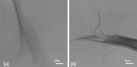
Fig. 3 illustrates laser-scribed surface of graphene oxide, indicating how the laser scribe method works. Graphene synthesis and giving the supercapacitor pattern are occurred simultaneously, which is considered to be the principal advantage of this method. Laser beam diameter is approximately 19.9 μm and the distance between adjacent scratches is about 4.6 μm. The re- duction of GO is clearly seen in Fig. 3(c) and Fig. 3(d). Fig. 3(c) demonstrates the formation of graphene sheets, and generally the plane state is observable, and the Fig. 3(d) shows that these formed sheets possess a distance between them and are not stuck together so that ionic exchanges and relocations are carried out. Although it should be considered that the scanning electron microscope( SEM) does not possess the magnification of showing an atomic layer, and these layers are not actually one layer of carbon atom. In fact, this graphene is multilayered in which, for instance, 10 layers of carbon atom or graphene atom have been stuck together.
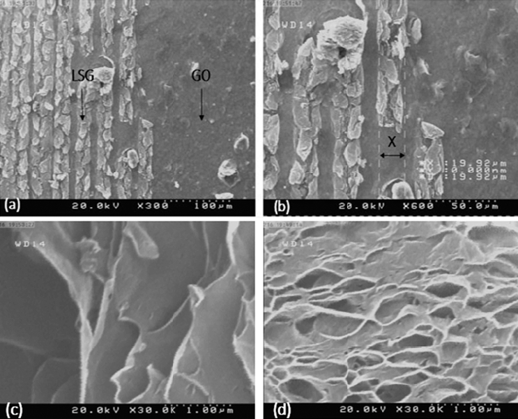
Fig. 3
SEM images of the laser scribed surface of graphene oxide at a low (a) and a high (b) magnification. Reduction of GO and the formation of graphene sheets (c) with a clear distance between them (d).
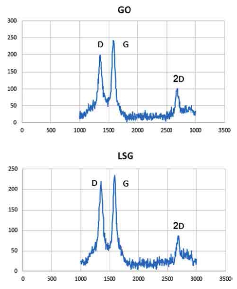
Raman spectroscopy was used to evaluate the GO reduction during the laser-scribing method. The Raman spectra of GO and LSG are shown in Fig. 4. Both GO and LSG exhibit typical disorder D band at around 1350 cm−1. Graphitic G band and amorphous 2D band existing at 1585 cm−1 and 2630 cm−1 can also be found in both GO and LSG. However, the present LSG has a lower structural sp3 defects as there is a slight increase in relative intensity of ID/IG after laser scribing.30,31)
In order to analyze the supercapacitance characteristics of LSG, their electrochemical properties have been investigated. For this purpose, the CV curves were taken between cut-off voltages of 0 and 1 V vs. Ag/AgCl reference electrode at different scan rates ranged from 10 to 200 mV s−1. These curves are shown in Fig. 5. Along with extension of current range, the area of the curve increases which refers to the ideal capacitive behavior of electric double-layer capacitors(EDLCs) over the applied scan rates. It can be observed that the total currents increase with increasing the scan rates.
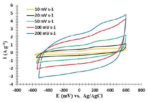
Fig. 5
The CV curves of pristine rGO at scan rate of 10, 20, 50, 100 and 200 mV s−1 in a voltage range of 600 and −600 mV in a three electrode system.
Based on the CV curves of Fig. 5, it could be understood that fabricated supercapacitor possesses a stored power, and it could be seen at various voltages after testing for 5 times. Since this is a V-I diagram and the internal area of diagram indicates the stored power (P = V.I), it could be mentioned assertively that a supercapacitor has been fabricated.
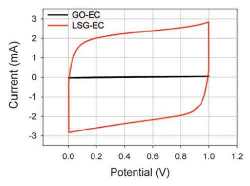
By comparing this CV patterns with a similar work of Maher F. El-Kady et al.20) which has been illustrated in Fig. 6, based on the inner area of the V-I diagram that is equal with the storing power, it could be concluded that this manufactured supercapacitor possesses a higher storage power.
The specific capacitance(F g−1) of different electrodes are calculated based on the following equation32):(1)
where I refers to thedischarge current density(A g−1), Δt is the discharge time(s), and ΔV is the discharge potential range(V).
The galvanostatic CC curveshave been illustrated in Fig. 7. It is obvious that the specimen has absorbed the energy and returned it to the circuit which has been tested twice. For determining the specific capacitance of this specimen, the following calculations have been made:
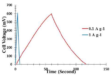
Fig. 7
Charge-discharge curves of pristine rGO at current densities of 0.1 and 1 A g−1 in a voltage range of 0 −600 mV in a three electrode system.
The specific capacitance of specimen has reached the amount of 10 F g−1 and has the capability to function as a supercapacitor.
Fig. 8 indicates Galvanostatic charge/discharge(CC) curves of an LSG-EC measured at a high current density of 10 A.g−1 LSG/electrode based on the research done by Maher F. El-Kady et al.20) In comparison with our study, it could be mentioned that CC curves measured at low current densities like 0.1 or 1 A.g−1 possess a higher discharge time, therefore, it could be claimed that lowering discharge current density results in higher discharge time range.
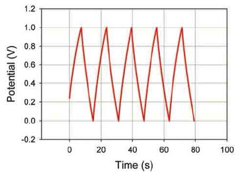
Fig. 8
Galvanostatic charge/discharge (CC) curves of an LSG-EC measured at a high current density of 10 A/g LSG/electrode.20)
The long-term charge-discharge stability of the LSG have been also investigated over 1000 cycles at a current density of 0.5 A g−1 between cut-off voltages of 0 and 1V vs. Ag/AgCl reference electrode. The results are illustrated in Fig. 9 As it is seen in this diagram, the specific capacitance has decreased very slightly from its primary capacitance of ~ 10 F cm−3 and the line in diagram has remained approximately steady. Although it has been investigated up to 5000 cycles, 1000 cycles performance is usually considered important in the analysis, and based on our diagram, its cyclic stability is favorable over 1000 cycles which indicates that the product is able to possess high efficiency.
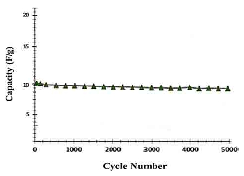
Fig. 9
The long-term charge-discharge stability of pristine rGo (a) at current density of 0.5 A g−1 in a voltage range of 0 and 1000 Mv in a three electrode system.
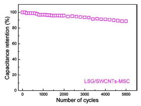
The long-term charge-discharge stability and capacitance retention over 5000 cycles was investigated by Wen, Fusheng, et al.29) for LSG/SWCNTs-MSC as it is shown in Fig. 10. By considering our resultant stability diagram, Fig. 9, and comparing with the results of Fig. 10, it could be mentioned that capacity decrease in Fig. 10 after 1000 cycles is a bit higher than what we have achieved in Fig. 9. The capacity retention in our study reaches approximately 95 % after 1000 cycles which is quite satisfactory and close to the optimal amount of 98 % after 1000 cycles.
According to the advantages mentioned above, fabrication of laser-scribed micro-supercapacitor electrode was accomplished by using this solution. The fabricated rGO micro-supercapacitor electrode(Fig. 8) is composed of 20 interdigitated electrodes of rGO, which are separated from each other by insulating spacers of GO. Fig. 11 indicates a flexible electrode which can be utilized in portable equipment.
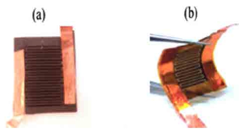
Fig. 11
(a) Optical image of rGO micro-supercapacitor electrode, (b) an optical photograph showing the flexibility of the electrode.
A comparison of the volumetric specific capacitance of the fabricated LSG supercapacitors has been provided in Table 1. The cross section image of the LSG exposes a thickness of about 7(μm). The volumetric capacity of LSG supercapacitors was computed based on the areal capacitance and the cross section image. Table 1 suggests that LSG supercapacitors has superior electrochemical properties in comparison to the pristine LSG and LSG/ CNT composite.
Table 1
Comparison of the specific capacitance of LSG sup ercapacitors produced by various methods with the fabricated MSC in this work.
| Electrode material | Specific capacitance (Fcm−3) | Reference |
|---|---|---|
| LSG/CNT | ~6 | [25] |
| LSG | ~8 | present work |
4. Conclusions
LSG supercapacitors were successfully processed by laser irradiation of graphene oxide on the DVD disks. Raman and XPS results confirm that the laser irradiation properly reduce GO to graphene sheets. As the sharp peak of 2D band in Raman spectrum presents, fabricated sheets have few layers. The performance of LSG supercapacitors as promising candidates for supercapacitor bulk electrodes and micro-supercapacitors were confirmed by galvanostatic CC and CV experiments. The present results prove that LSG flexible micro-supercapacitors offer higher specific capacity(8 F cm−3) at both high and low current densities than pristine graphene electrodes(2-3 F cm−3). In this study, a product was fabricated in which formation of GO sheets was observed using TEM, and graphite became laminate. The formation of graphene sheets was then observed by applying laser with SEM. Graphene quality was very well evaluated by Raman spectroscopy, and the synthesis of graphene could be proved which helped to claim that a supercapacitor has been fabricated. The CV curves of pristine rGO at various scan rates showed that the ultimate product has the power of storing energy in a supercapacitor level. Chargedischarge curves of pristine rGO at two different current densities indicated that specific capacitance(Cm) increases by reducing discharge current density. Finally, the longterm charge-discharge stability of the LSG was plotted which indicated that specific capacitance has decreased very slightly from its primary capacitance of ~10 F cm−3 and its cyclic stability is favorable over 1000 cycles.