

1. Introduction
Cast is commonly used for fracture management and postoperative fixation in pediatric patients.1) However, fixing the fracture site with a cast can cause complications such as thermal injuries, pressure sores, infections, stiffness, and neurovascular injury. Wearing a cast may also cause constraints of daily life and other complications.2) In addition, applying casts by inexperienced practitioners can increase the risk of being loose and can result in time and cost for removing them. To minimize disadvantages of a cast that has been conventionally used, waterproof casts for bathing or swimming and auxiliary splints for managing fractures and avoiding other complications have been developed.
Cast is a tool that provides overall support for the fractured bone to keep the bone safe during treatment. Splint is a limited tool that provides partial support for wrist joints, for example. An ideal method and material selection for applying cast and splint can prevent patient morbidity and reduce complications caused by casting and splinting.2) Various types of dressings such as soft dressing, plaster splint, plaster cast, and fiberglass cast can be applied to heal surgical injuries immediately and quickly.3) Determining which type of dressing to be used depending on the type and duration of postoperative dressing has a significant impact from the initial recovery stage to the outcome of the patient. Splint is a tool used to speed up healing by fixing bone fractures and parts of the body after surgery.4) It is also used to treat various chronic diseases that affect hands and wrists. It can temporarily alleviate acute injuries and promote comfort and healing after surgery.5)
Although there are various techniques for dressing an injured part of the wrist, plaster splint is mainly used by making wrist splint with ten layers of bandages. Wrist splint is often made of fiberglass or plaster of different thicknesses. Fiberglass splint is recently being used more than plaster splint. Fiberglass splint is more commonly referred to as synthetic splint. It is generally made of fiberglass material, a type of moldable plastic.
Chow et al.6) have compared functions of plaster splint and fiberglass splint. They prepared a plaster splint with warm water (50 ~ 55 °C), manually compressed the splint bandage material (BSN Medical, Hamburg, Germany), and then let it dry with the index finger and middle finger connected. They made a fiberglass splint (BSN Medical) with warm water (20 ± 2 °C) using fiberglass material. As a result, the plaster was easy to use in a sudden environment such as a fracture and in a large fracture site. However, such fiberglass plaster had swelling properties.
Splint used for hands must be strong, not heavy, have efficiency and safety, and must be simple and clean in appearance.7) Studies are ongoing to efficiently evaluate these characteristics. Although study results of elastic modulus, yield strength, and tensile strength tests of cast materials for plaster bandage and fiberglass bandages have been reported so far,8-10) studies on morphological characteristics of these materials and changes in physical properties caused by wear are insufficient. In particular, the low tensile strength of a splint can lose stiffness of the material over time.11) In addition, dressing during the use of plaster may cause fracture displacement and uncomfortable pain due to wear.6)
As part of a study on morphological characteristics of splint and cast, prepacked fiberglass splint and cast were selected as experimental materials in the present study. Their microstructural characteristics were analyzed and compared with a scanning electron microscope (SEM). Each composition was then analyzed with an energy dispersion X-ray spectrometer (EDX).
2. Materials and Methods
2.1. Experimental Materials
Fiberglass splint (RoboTM splint, S&F Inc., Korea) and fiberglass cast (ScotchcastTM, 3M, Korea) used in general hospital orthopedics and emergency rooms were used as experimental materials. To verify material properties and constituent elements of splint and cast, they were cut into 1 cm2 each with experimental scissors and a razor on a clean bench (Biosafety type, CB-800CB, Supermax, Korea).
2.2. Scanning Electron Microscopy
To confirm the fine morphology of the plaster and fiberglass added to fiberglass splint and fiberglass cast, each 1 cm2 samples were dried in a vacuum dryer (60 °C, HMDS-6210, Hasuc, China) for 36 h. Each dried sample was coated with platinum to a thickness of 10 nm using an ion coater (IB-5 ion coater, Eiko, Japan) while being placed on a stub covered with copper tape attached on top of a carbon tape. Platinum-coated samples were then mounted on a scanning electron microscope (S-4700, Hitachi, Japan) and observed at 15 kV.
2.3. Energy Dispersive X-ray Spectrometry
To analyze constituent elements of fiberglass splint and fiberglass cast, each splint sample cut into 1 cm2 was attached to a stub attached with a carbon tape and then coated with platinum to a thickness of 10 nm using an ion coater (IB-5 ion coater, Eiko, Japan). These plated samples were analyzed with an energy dispersive spectrometer (Energy Dispersive X-ray Spectrometry, INCA, Oxford Ins, Great Britain) at an acceleration voltage of 15 kV.
3. Results
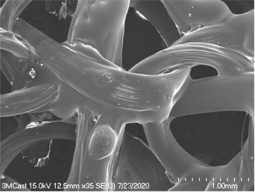
Fabric structure of the fiberglass splint was observed under a scanning electron microscope (Fig. 1). Fiberglass bundles like thin threads were well assembled in a scanning electron micrograph at low magnification. The fabric woven by fiberglass bundles had a porous structure (Fig. 1). Empty spaces between fiber bundles were observed in the form of triangles or ellipses of varying sizes. The long-axis diameter of the triangular space between fiber bundles in the fabric of fiberglass splint was measured at about 1 mm. These porous structures were very dense. They were formed in a constant structure (Fig. 1).
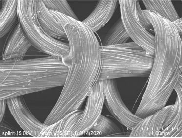
Fig. 1
Low magnification scanning electron micrograph of fiberglass splint. The fabric of the fiberglass is well woven.
The surface of fiber bundles of the fiberglass splint was covered very thinly with plaster. Fiber bundles covered with plaster showed a distinct outline of each fiberglass strand (Fig. 2). The gap between these separated fiberglass was measured up to 100 μm, with glass fibers being separated from each other on some surfaces of fiberglass bundles thinly covered with plaster (Fig. 2).
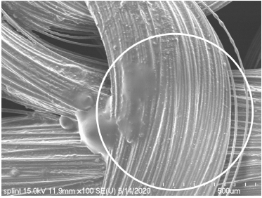
Fig. 2
Scanning electron micrograph of a bundle of fiberglass splint. The plaster is thinly covered on a bundle of fiberglass splint (circle).
In Fig. 3, a fiberglass bundle covered with plaster was measured at 583 μm in diameter. Most bundles were measured at 600 μm in lateral diameter. Single strand of fiberglass partially separated from the surface of the bundle was also covered with plaster. Their diameters were measured at 8.5 μm to 10 μm in thickness. In addition, the covered surface was smooth or slightly rough (Fig. 4).
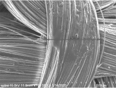
Fig. 3
Scanning electron micrograph of a bundle of fiberglass splint showing that a width of a fiberglass bundle of 583 μm.
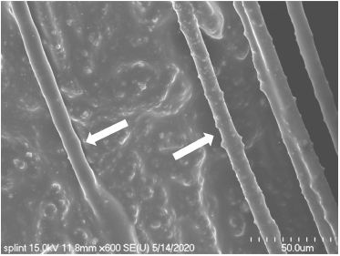
Fig. 4
Scanning electron micrograph of fiberglass (arrows) separated from a bundle of fiberglass splint.
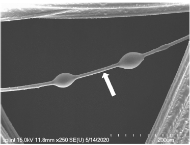
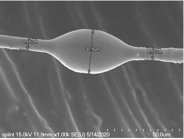
On the fiberglass surface independently separated from the bundle, a region where the plaster was thinly covered with a constant thickness and bead-shaped structures formed as plasters were bonded to each other (Fig. 5). The stiffened bead-shaped plaster covering the fiberglass had a lateral diameter of 20.9 μm to 30.9 μm (Fig. 6).
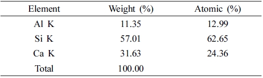
Constituent elements of the fiberglass splint were analyzed by an energy dispersive spectrophotometer. Calcium (Ca), aluminum (Al), and silicon (Si) elements were detected in the fiberglass splint (Fig. 7). Contents of these constituent elements were: 62.65 % for Si, 24.36 % for Ca, and 12.99 % for Al in the order of Si > Ca > Al (Table 1).
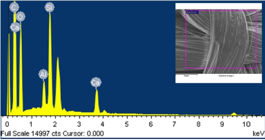
Fig. 7
EDX spectrum of fiberglass splint. EDX reveals Si, Ca, and Al elements present on fiberglass splint. Inset shows detection area of fiberglass splint surface for EDX.
The fabric texture of the fiberglass cast was observed with a scanning electron microscope (Fig. 8). In scanning electron microscopy at low magnification, fiberglass bundles of fiberglass cast were completely covered with the plaster. The fiberglass was not exposed or separated from bundles (Fig. 8). The lateral diameter of a fiberglass bundle in the cast was measured at about 700 μm. A space formed between knots appeared in the form of a triangle with gentle edges. The long-axis diameter of such space was measured 1 mm to 1.4 mm (Fig. 8).
A fiberglass bundle of the cast had a very smooth surface without any exposure or separation of the fiberglass by being completely covered with the plaster (Fig. 9). The fiberglass partially protruding on the surface of the fiberglass bundle was also completely covered with the plaster (Fig. 10). In scanning electron microscopy observation at high magnification, the surface of the region where the fiberglass protruded was observed to be very smooth (Fig. 11). In some regions, swollen areas were also observed between the fiberglass bundle and the stiffened plaster (Fig. 12). A single strand of fiberglass covered with the plaster in the fiberglass cast was measured at 11.5 μm in lateral diameter (Fig. 13).
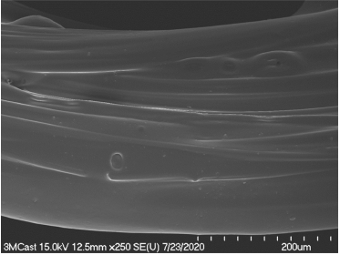
Fig. 9
Scanning electron micrograph of bundles of the fiberglass cast. The surface of a bundle covered with plaster appeared to be smooth.
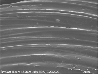
Fig. 10
Scanning electron micrograph of bundles of the fiberglass cast. The plaster thickly covered a bundle of the fiberglass cast.
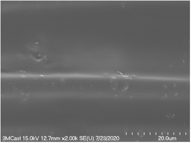
Fig. 11
Scanning electron micrograph of the surface of a bundle of the fiberglass cast. The surface was observed to be smooth.
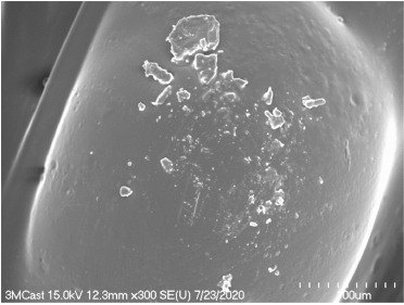
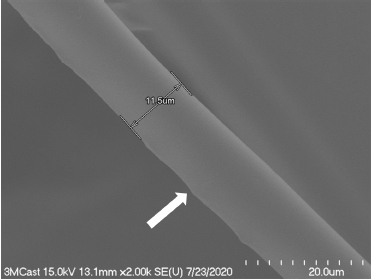
Fig. 13
Scanning electron micrograph of a single strand of fiberglass, showing that the fiberglass has a short axis diameter of 11.5 μm.
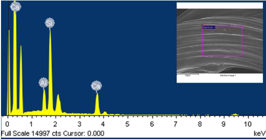
Constituent elements of the fiberglass cast were analyzed with an energy dispersive spectrophotometer. Calcium (Ca), aluminum (Al), and silicon (Si) elements were detected in the fiberglass splint (Fig. 14). Contents of these constituent elements were: 61.12% for Si, 25.78% for Ca, and 13.11% for Al in the order of Si > Ca > Al (Table 2).

4. Discussion
Splinting can be used as a temporary measure for fractures and dislocations of limbs and soft tissue damage. It is mainly used during transport of emergency patients. It can also reduce pain by fixing damaged unstable limbs. It can prevent further dislocation and surrounding tissue damage.12) Casting is the most common fixation technique used in the management of acute fractures of distal biceps. It can be used to prevent fracture displacement and heal callus formation and fractures.13)
Over the past few centuries, the Plaster of Paris has been used to fix fractures with advantages of being affordable, easy to mold, and easy to purchase. However, the applied area can become messy and heavy. In addition, it takes a long time to make the applied area strong enough.14)
Recently, fiberglass and polyester are used as materials for casting and splinting. Although various types of cast can cause skin irritation in almost similar proportions, synthetic casts have high durability and convenience. It is also effective and easy to remove them.12)
In this study, fiberglass and cast were well-organized fabric structures that formed triangles or oval holes between these fibers. The long-axis diameter of the space formed between knots of the fabric. The splint was formed up to 1 mm and the cast was formed up to 1.4 mm. This porous structure can reduce irritation to the skin. In addition, it is easy to remove. Callahan et al.15) have reported advantages of synthetic casting, including high strength, high porosity, light weight, and effective radiation permeability.
Using prepackaged fiberglass splints is an easy way to quickly treat and manage patients with injured limbs in an emergency room.12,16) The prepackaged fiberglass splint used in the experiment in this study was covered with plaster thinner than the fiberglass cast. The surface of the fiberglass splint bundle was confirmed to have protruded fiberglass, whereas the surface of the fiberglass cast bundle was observed to have a smooth surface because the plaster was thicker than the sprint. Splint is used for comfort in the pre-treatment stage as a temporary measure for wrist and hand dislocations or fracture subluxations. Cast is used to prevent fracture displacement and heal acute fractures. Therefore, it is speculated that more plaster is added to the cast.
The material of a synthetic cast and splint is composed of open polyester impregnated with a water-activated polyurethane resin. The material of the cast made of polyurethane prepolymer is activated by application of water which causes an exothermic reaction that stiffens a cast.14) Both are preferred for their ease of application, lightweight properties, strength, and radiation permeability.17,18)
In this study, the thickness of each fiberglass in the fiberglass splint and cast covered with plaster was about one tenth of the thickness of a hair, having a maximum diameter of 11.5 μm and 10 μm, respectively. Such slight difference in the thickness of fiberglass between cast and splint was due to difference in the amount of plaster covered on the fiberglass. Polyurethane resin is widely used in industries such as mining, oil fields, machinery, transportation, and construction due to its excellent physical, chemical, and mechanical properties.19)
In this study, as a result of analyzing constituent elements of fiberglass splint and cast, Ca, Si, and Al elements were detected. Although there was a very small difference in the content ratio, they were molded by the exothermic reaction caused by the content of the plaster as they became dry.
5. Conclusion
In this study, as a result of observing the texture of the fabric of fiberglass cast and splint and the shape of the covered plaster with a scanning electron microscope, it was confirmed that both fiberglass cast and splint were woven into a constant structure with well-formed empty spaces between bundles. The fiberglass cast was observed to be exposed or separated from bundles because the thickness of the covered plaster was thinner than the splint. It was also observed that the cast was smoother than the fiberglass splint on the surface of the stiffened plaster. Although there was a slight difference in content ratio between the fiberglass splint and the cast, it was confirmed that they were composed of Ca, Si, and Al elements. In conclusion, prepackaged fiberglass splint and cast were found to have a different amount of plaster added according to their respective applications.
