

1. Introduction
The light is including the vital section to the daily life of human organizations. Before the advent of artificial lighting, humans used sunlight to illuminate the day and use only candles to illuminate the night. At the end of the 19th century, the first commercial lighting technology based on natural gas was introduced. Thomas Edison invented the light bulb in 1879, which heated the light to make it glow when an electric current passed through the metal wire. Then, fluorescent tubes and compact fluorescent lamps emerged with the gradual evolution of electronic lighting technology, it has become widely available in the 1950s and early 1990s, respectively. Power shortages are a major problem in the world today. So, people need technical help to reduce electricity consumption. Therefore, one of the rapidly developing technologies with significant energy saving was emerged in the 20th century. That developing technology is LED technology.1)
LED is a semiconductor device that converts electricity directly into light, when an electrical current is flowing through it, an electron and a hole radiatively recombine emit a photon (light). LED device effective facts are energy saving, low energy consumption, easy use, no expensive cost and brighter and smarter than the incandescent light sources and fluorescent light sources. But conventional LED has the problem. This problem is low light extraction efficiency with no all light escape into the air because light trap in the semiconductor by the total internal reflection. The total internal reflection is caused by the high difference of refractive index between LED semiconductor material and encapsulant materials.2,3) Various methods to resolve this problem of LED include LEDs with textured surfaces, LEDs with photonic crystals, LEDs grown on patterned substrates, and LEDs coated with patterned gradedrefractive- index coatings.4-6)
J. K. Kim et al. demonstrated multilayer gradedrefractive- index pillars that increased light output by 73 % by eliminating total internal reflection to increase light-output performance.4) A. N. Noemaun et al. have proposed and demonstrated GRIN diamond-shaped pillars and an array of GRIN cylindrical pillars patterns that enhance 131 % and 104 % light-output power than comparison to the planar reference device.5) LEDs patterned with TiO2 micro-pillars with tapered having 100 % enhancement in light-output power over planer LEDs has been reported by M. Ma et al..6) M. Ma et al. designed LEDs patterned with an array of four-pointedstar- shaped GRIN micro-pillars to enable control of emission pattern and this result a 155 % enhancement lightoutput power over an uncoated planar reference LED.7)
The aim of this study is to optimize the light emit of GaInN LEDs elimination the total internal reflection from the large refractive-index contrast between the LED semiconductor and air. A complete solution for this problem needs advanced and detailed control of the refractive index at the LED semiconductor and enhancing the total range of extracted angles from the semiconductor.4) The critical angle at the interface is only 23.57° between the refractive index of semiconductor ns = 2.5 is surrounded by air, refractive index of air nair = 1. Therefore, the transition of light through the planar surface to the escape cone is limited by the critical angle. The other light ray incident between 23.58° and 90° is completely reflected back inside the semiconductor. To achieve the purpose of this paper by removing the TIR, the refractive index of the graded-refractive-index (GRIN) coatings micropillars is calculated with various compositions and the critical angles of each layer are calculated based on these refractive indices of each material.
2. Materials and Methods
2.1. Design of the GRIN Layer with Various Composition of (TiO2)x(SiO2)1−x material
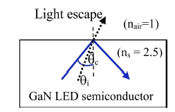
The normal planar LEDs cause total internal reflection (TIR) which have only one interface between the LED semiconductor GaN (ns = 2.5) and air (nair = 1) with high refractive index contrast. According to Snell’s Law, nssinθ1 = nairsinθair only those light rays are escape the semiconductor at the angle less than the critical angle
can be transmitted to the surrounding medium and the light rays at the incident angle (θi) larger than the critical angle (θc) will be totally reflected as shown in Fig. 1.6)
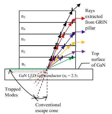
So, this research uses the Graded-refractive-index (GRIN) technology to eliminate the TIR. The GRIN pillar uses of five dielectric layers made of (TiO2)x(SiO2)1−x with various composition that refractive index with a decreasing refractive index as the pillar height increases. The refractiveindex of button layer is adjacent to the semiconductor (the highest refractive index) and the top layer is match to air (the lowest refractive index).6,7,16) The GRIN coatings have been widely used as antireflection (AR) coatings in optical devices such as solar cells and light-emitting diodes (LEDs). The GRIN is very well appropriated to encourage light extraction and can eliminate TIR inside the LED semiconductor.7,8,17) As shown in Fig. 2, the gradedrefractive- index (GRIN) coatings that form of multiple dielectric layers having refractive indices (n) which gradually decline from the substrate to the surrounding medium as the following pattern:
2.2. The Refractive Index of (TiO2)(SiO2) with Molar Ratio
The refractive index (n) of the dielectric layer (TiO2 SiO2) is dependent on the volume fraction TiO2 in this mixture. Five-layer of different volume ratios of TiO2 and SiO2 are deposited to form graded-refractive-index layers as the follow: Firstly, ‘x’ is the molar fraction of dielectric material of layer is calculate by using eq. (3) and eq. (4). are weight fraction of TiO2 and SiO2 and are atomic mass of TiO2 and SiO2. And the volume fraction TiO2 in this mixture is compute eq. (6) and eq. (7). Vi is the molar volume of total component and V1 and V2 are the molar volume of TiO2 and SiO2, respectively.9,10)
Arago-Biot (A-B):
Gladstone-Dale (G-D):
Lorentz-Lorenz (L-L):
Newton (Nw):
Eyring and John (E-J):
The refractive index (n) of the dielectric material:
The effective refractive index:
After that the calculation of the refractive index value of the mixture used by eq. (8) to eq. (14). The symbol of n1, n0, , are the theoretical refractive indices and volume fraction of TiO2 and SiO2, respectively.11,12) Then, the refractive index value of next layer’s mixture is calculated using this procedure. If the molar fraction value in the material is different, the different refractive index value of that material is got.
2.3. Transmittance value of GRIN encapsulation and Optimum for Light Extraction Efficiency
As light rays are incident upon a boundary between two different refractive indices materials, multiple reflection loss and transmittance values will contribute. Calculating reflection loss and transmittance values at each interface that can be expressed in terms of the Fresnel transmittance as13,18)
For multiple reflections within a layer bounded by refractive index contrasts, we analytically search that the total transmittance for L layers can be expressed as14,15)
where ns and nL+1 are refractive index values of the semiconductor and air, respectively, with n1, n2, … nL as the graded layers following n0.
As the number of layers increases due to the drastic reduction of the Fresnel reflection, the optical transmittance increases significantly. Then, the efficiency of light extraction can be evaluated by considering the critical angle given to the total internal reflection given by Snell's law in the following equation:16.19)
3. Results and Discussions
3.1. Simulation of Five-layer GRIN Coatings Pillar Light Emitting Diodes
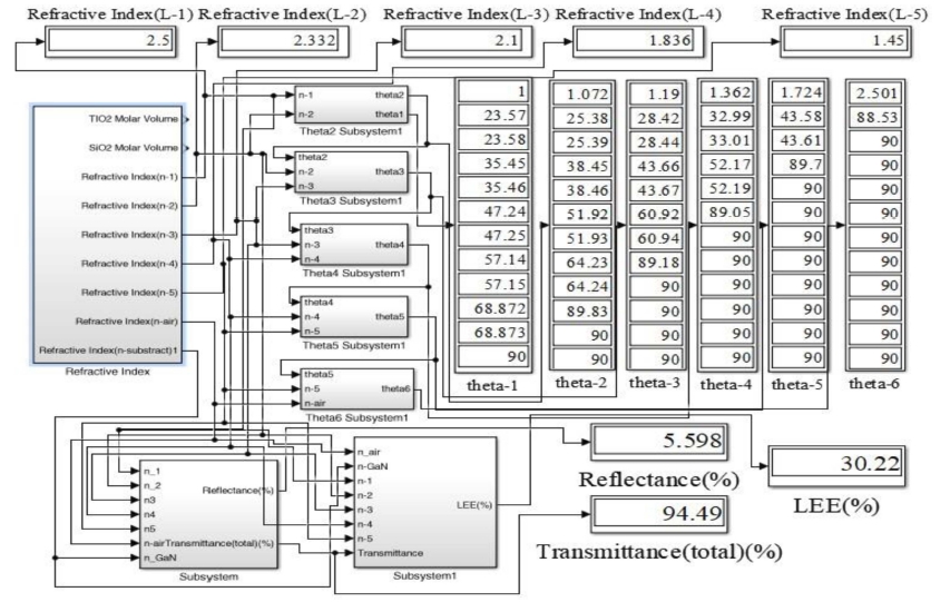
These are the important parameters of GRIN LEDs. To achieve better performance of light, it is essential to design the layer of GRIN pillar LED with the appropriate value of parameters. These parameters provided for enhance the extracted light and those have to be determined. Some of the important parameters can be calculated in characteristics equations by MATLAB Simulink. The following parameters are simulated in MATLAB Simulink.
3.2. Evaluating the Variable Compositions of TiO2 and SiO2
In LEDs, the refractive index plays a key role in avoiding TIR. The refractive index of the material varies due to the different molar fraction values. All the weight fraction values of each component in every material are sum is ‘unity’ according to theory. To eliminate large difference in refractive index between the GaN subtract and air, added the multilayers on the GaN subtract. During the sputtering of TiO2 and SiO2 targets, (TiO2)x(SiO2)1−x layer with a desired x value is achieved by tuning weight fraction. In the stacking layers, the bottom layer uses TiO2 and the upper layer uses SiO2 which matches refractive index of air.
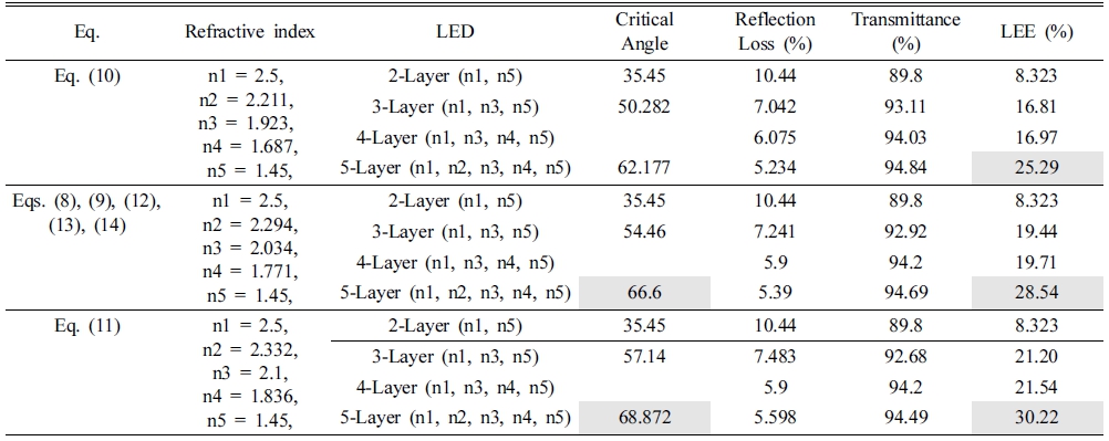
Atomic mass of TiO2 is 79.866 g/mol and atomic mass of SiO2 is 60.08 g/mol are used in the refractive index solving equations and then calculated the volume fraction. According to theory, the sum of the volume fraction of all materials in the mixture is equal to ‘unity’. This research compares the refractive index of each layer in the GRIN structure calculated by 7-equations. Table 1 shows the relationship of weight fraction to molar fraction, molar fraction to refractive index and appear the refractive index of five-layer by calculation 7-equations.
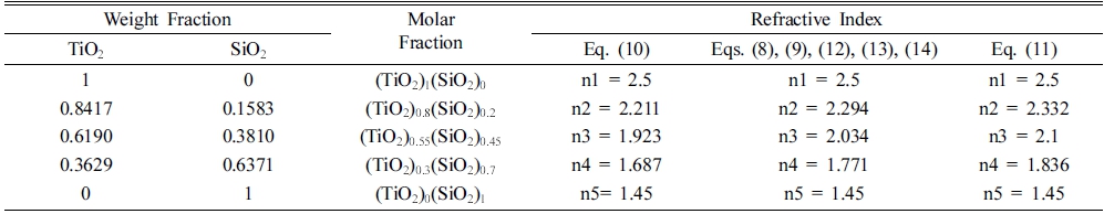
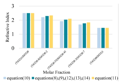
The refractive index of material with the same molar fraction is evaluated by using 7-equations. The refractive index of first-layer and fifth-layer are the same. But, the refractive index of second-layer, third-layer and fourthlayer are differed and remain 3-types of results. Eq. (10) get the lowest value, eq. (11) receive the highest value of these 3-types. And, other methods remain the same value of refractive index and these values are medium among them. These results performance in Fig. 6.
3.3. The Extracted Angles of the Emitted Light Resolved by Incident Angle
Snell's Law states that the ratio of the angle of incidence to the angle of refraction of a light as it travels through a boundary between two media is a constant termed the refractive index. So, after the refractive index of layers calculated, the extracted angles of consecutive layer and light can be emitting through the sidewalls of any layer compute using Snell’s law.
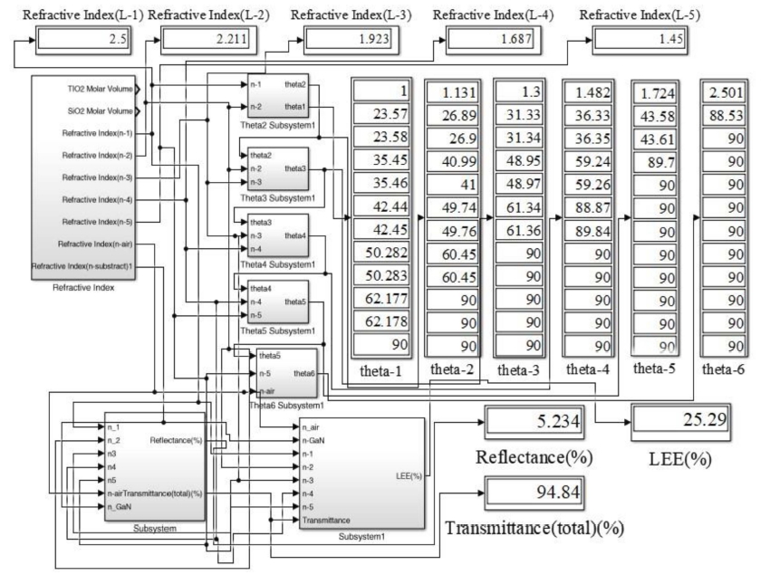
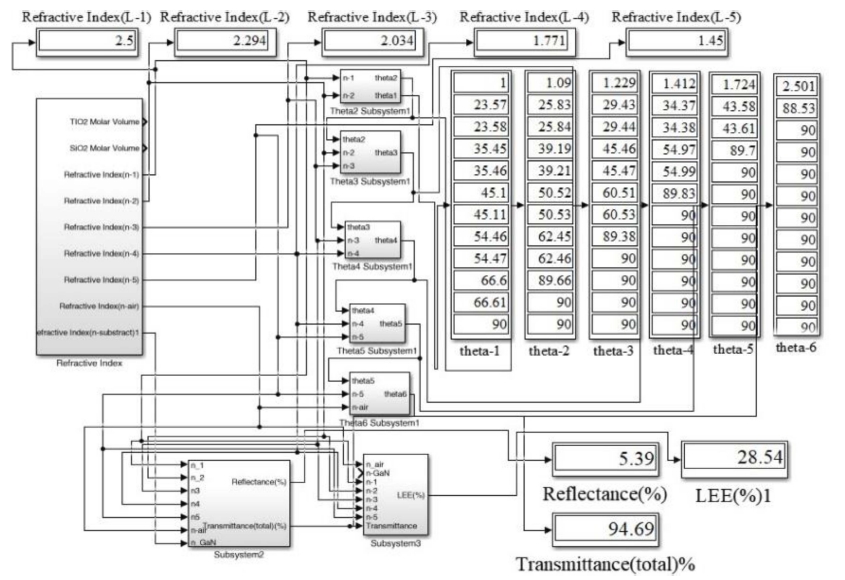
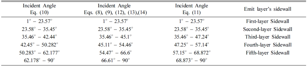
Table 2 shown the comparison of layer’s sidewall with extracted angle at the different multilayers using 7-equations. In 5-layers design, the light is emitted the incident angle during 23.58° to 35.45° [eq. (3)], 23.58° to 35.45° [eqs. (8), (9), (12), (13), (14)], 23.58° to 35.45° [eq. (11)] through second-layer’s sidewall, during 35.46° to 42.44° [eq. (3)], 35.46° to 45.1° [eqs. (8), (9), (12), (13), (14)], 35.46° to 47.24° [eq. (11)] through third-layer’s sidewall, during 42.45° to 50.282° [eq. (3)], 45.11° to 54.46° [eqs. (8), (9), (12), (13), (14)], 47.25° to 57.14° [eq. (11)] through fourth-layer’s, during 50.283° to 62.177° [eq. (3)], 54.47° to 66.6° [eqs. (8), (9), (12), (13), (14)], 57.15° to 68.872° [eq. (11)] through fifth-layer’s sidewall. According to Table 2, the design of the five-layer is the highest critical angle remain among them.
3.4. The GRIN LEDs for Light Extraction Efficiency Enhancement
The refractive index is calculated using eq. (11) remain highest refractive index in each layer and most enhance the light extraction efficiency. Using eqs. (8), (9), (12), (13), (14) receive the same value of refractive index value and these are the medium value among these 7- equations. Finally, eq. (10) get the lowest refractive index and LEE as shown in Table 3.
Then, calculated reflection loss and transmittance at for GaN/air, GaN/TiO2/air, GaN/SiO2/air, and GaN/GRIN/air, respectively and we assume that the refractive index varies from 2.5 to 1.45 for the GRIN multilayers.
The aim of this research is to obtain high light extraction efficiencies. If the stack layers consist of multiple layers with refractive-index values that gradually decrease, transmittance will be higher. Light extraction through the pillar increases with increasing number of GRIN layers due to reduced Fresnel reflection loss as shown in Fig. 7, Fig. 8 and Fig. 9.
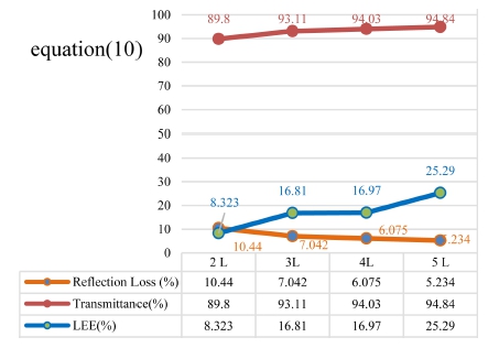
Fig. 7
Demonstration of refraction loss, transmittance and light extraction efficiency made using the refractive index value remain result from eq. (10).
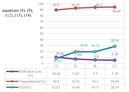
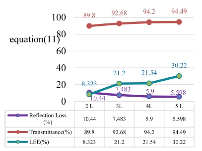
Fig. 9
Demonstration of refraction loss, transmittance and light extraction efficiency made using the refractive index value remain result from eq. (11).
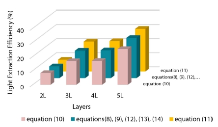
Optical transmittance is enhanced as the number of layers increases for the graded refractive index layers and the five-layer get the enhanced LEE. Fig. 10 is comparison of light extraction efficiency of GRIN multilayers with 7- equations. The LEE of GaInN LEDs with 2-layer GRIN design is 8.323 %, which are the same using 7-equations. And, 3-layer and 4-layer GRIN design are 16.81 %, 16.97 % [eq. (10)], 19.44 %, 19.71 % [eqs. (8), (9), (12), (13), (14)] and 21.20 %, 21.54 % [eq. (11)] of LEE. The LEE of five-layer is 25.29 %, 28.54 % and 30.22 %, which value using the 4-types of layers is highest the light-extraction efficiency of them. Therefore, the fivelayer GRIN design is the most suitable for the enhance LEE value design.
4. Conclusion
In summary, the GRIN coating has tuned by control the refractive index values to avoid the total internal reflection of light emitting diodes. A method called gradedrefractive- index (GRIN) technology, which completely eliminates the total internal reflection of GaInN LEDs to improve the light output efficiency. This research creates on the modeling and simulation of LED with GRIN pillars for the purpose of providing the ability to predict the efficiency of different layers. These GRIN layer made of (TiO2)x(SiO2)1−x material, the refractive indices of (TiO2)x(SiO2)1−x of five-layer with various composition of molar ratio are represent. In addition, the refractive index values each layer of pillar are analytical calculated, Simulink design and compute the specific range of light incident angles at the individual layers of the five-layer GRIN LED. According to calculations, the same molar material using refractive index solving 7-equations remain 3-types of refractive index five-layer GRIN remain 25.29 %, 28.54 % and 30.22 % respectively. The escape cone of the five-layer GRIN LED is enhanced the LEE compared with the planar reference LED, which include the interfaces between the sidewall of each layer and air. So, the five-layer GRIN design is improving the light extraction efficiency.
