

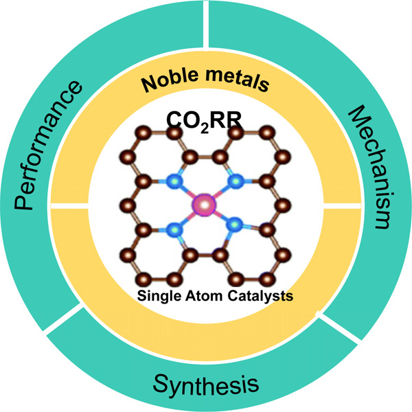
1. Introduction
2. Fundamentals of the CO2RR on SACs
2.1. Mechanism of CO2 to CO conversion
2.2. Parameters
3. Electrocatalytic Performance of SACs for CO2RR
3.1. Noble-metal-based SACs
3.2. Non-noble metal SACs
4. Conclusion
1. Introduction
Carbon dioxide (CO2) concentration in the atmosphere have been increasing drastically in the past few decades owing to the reckless use of fossil fuels, causing severe consequences of climate change and environmental issues.1,2) With the growing importance of renewable energy sources, efforts have been made to develop alternative energy technologies. CO2-molecules can be converted into useful chemicals via thermocatalytic,3) photocatalytic4) and electrocatalytic reduction.5,6) Among them, the electrochemical reduction of CO2 is regarded as a potential approach to reduce atmospheric CO2 levels and simultaneously produce high-value-added products.7-9) However, the performance of CO2RR is generally hindered by thermally stable CO2 molecules, sluggish reactions, and competition with hydrogen evolution reactions (HER).10,11) In addition, the CO2RR involves multiple proton-coupled electron transfer steps, which can convert CO2 into various compounds such as carbon monoxide (CO), methane (CH4), formic acid (HCOOH), methanol (CH3OH), ethylene (C2H4), and ethanol (C2H5OH). Table 1 shows the CO2RR pathways and standard potentials against a standard hydrogen electrode in an aqueous medium.12,13) Therefore, the development of high-performance catalysts with great stability and selectivity is an essential prerequisite for achieving the desired electrocatalytic CO2 performance. Among various products from CO2RR, CO does not go through complicated reaction path compared to other multi-carbon products, resulting in high yield and high selectivity. Furthermore, as a component of syngas, CO is a crucial industrial material to synthesize a series of valuable chemical products for Fischer-Tropsch synthesis.14,15) Noble-metal-based nanoparticles such as Ag16,17) and Au18,19) have been found to be the best catalysts for reducing CO2 to CO at low overpotentials. Nevertheless, their scarcity and high price limit their large-scale applications,20,21) which has inspired researchers to downsize metal nanoparticles into isolated single atoms with improved electrocatalytic activity. In 2011, Zhang et al. first suggested the concept of single-atom catalysts.22) They used the co-precipitation method to fabricate a Pt single-atom catalyst that consists only of an isolated single atom embedded in iron-oxide, and the catalyst exhibited excellent performance for both CO oxidation and preferential oxidation of CO. Since then, single-atom catalysts (SACs), especially metal-nitrogen-carbon (M-N-C) structures, have drawn considerable attention from researchers and extensive experimental studies have been performed.23) A SAC is a noble metal or non-metal that is uniformly dispersed and unlike conventional catalysts, SACs generally feature isolated metal atoms anchored on support material as active sites, which maximize the efficiency of metal atom utilization by nearly 100 %.2,11,24,25) Furthermore, metal atoms are highly dispersed and result in a larger exposure of active sites, which leads to a significantly improved catalytic performance.26-29)
Table 1.
The potentials for the major electrocatalytic CO2 reduction reaction half reactions (at pH = 7).12,37)
In this review, we briefly discuss the mechanisms of CO2 to CO conversion. Recent advances in enhancing CO2RR performance using noble metals and transition-metal-based SACs are systematically summarized (Fig. 1).
2. Fundamentals of the CO2RR on SACs
Because CO2RR involves very complicated reactions, coupled with multiple proton-electron transfer steps, it is important to understand the reaction mechanism for designing efficient electrocatalysts.
2.1. Mechanism of CO2 to CO conversion
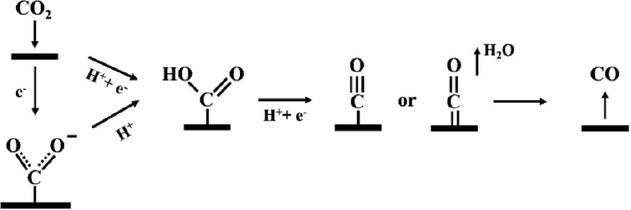
Carbon dioxide, the main reactant in the reaction, has a full 1 πg orbit and an empty 2πu orbit. Owing to its orbital structure, the oxygen in carbon dioxide serves as an electron donor, and carbon serves as an electron acceptor. Fig. 2 shows the reaction pathway for CO2 electroreduction to CO.29) To reduce CO2 to CO, CO2 is chemically adsorbed first on the surface of the catalyst to form a carboxyl intermediate (COOH*).30) The generation of COOH* occurs on the catalysts’ surface through a proton-coupled electron transfer step [Eq. (1)] or two steps of proton decoupled electron transfer [Eq. (2, 3)].11) COOH* will be further reduced to adsorbed CO (CO*) through another proton-coupled electron transfer, which is finally desorbed from the catalyst to release CO.10) The rate determination step (RDS) may be determined by the binding energy of CO2-* and COOH* as well as the desorption energy of CO*.15,31)
If the adsorption strength of CO* is very strong, the surface of the catalyst becomes poisoned and the HER becomes dominant.32) Thus, it is important to adjust the adsorption energy of the key intermediates to design optimal electrocatalysts for CO2RR, which should bind COOH* strongly and CO* weakly to promote both the COOH* formation and the CO* desorption steps.31)
2.2. Parameters
The turnover frequency, overpotential, faradaic efficiency, current density, and Tafel slope are used to evaluate the performance of the CO2RR electrocatalysts.
2.2.1. Turnover frequency (TOF)
The turnover frequency (TOF) is a measure of the efficiency of chemical reactions by catalysts, showing the activity of a catalytic site. It is used to describe the intrinsic activity of the electrocatalyst and can be characterized as the number of molecules reacting at each available catalyst site per time.33)
2.2.2. Overpotential (η)
The CO2 electroreduction reaction requires a voltage larger than the theoretical reduction potential due to various overpotentials, such as activation overpotential, concentration overpotential, and resistance overpotential. The overpotential (η) can be obtained from the difference between the theoretical cell voltage and the actual voltage required to cause an electroreduction reaction in the system.34) Minimizing overpotential while maintaining high activity is an important factor in the design of electrocatalysts.35-37)
2.2.3. Faradaic efficiency (FE)
Faradaic efficiency (FE) is another important parameter that shows the efficiency of electrons transfer in a system that promotes electrochemical reactions. It is calculated to determine how efficiently the desired product is produced, as various reactions occur in one electrode during CO2RR.37)
2.2.4. Current density
Because electrons participate in the CO2 reduction reaction, the degree of reaction can be calculated through the number of electrons shifting in a certain volume of space during specific time, that is, the current density. The current density is defined as the electric current per geometric area of the working electrode at a given cell potential, and the partial current density for the desired produce can be calculated by multiplying the total current density by the FE. The rates of the CO2 electroreduction reaction at the electrodes is proportional to the current density.38) The higher the current density, the higher the electrochemical reaction rate, and high-performance electrocatalysts must produce a high partial current density of the formation of the desired product.
2.2.5. Tafel slope
The Tafel slope is an important parameter to confirm the rate-determining step of the electrochemical CO2RR and to understand the reaction mechanism.39) This can be obtained from the graph of the logarithmic current density of a specific product and the overpotential. The gentler the Tafel slope, the better is the reaction.
3. Electrocatalytic Performance of SACs for CO2RR
3.1. Noble-metal-based SACs
Noble metals (Au, Pd, Ag, etc.) are reported to have a high selectivity for CO2 to CO because of their weak adsorption with the CO* intermediate. Atomically dispersing these noble metals into N-doped carbon substrates is a promising approach to enhance metal utilization and lower the cost of noble metals. He et al.40) investigated a palladium (Pd) single-atom catalyst anchored on nitrogen-doped carbon which is catalytically active for the CO2RR. Atomic-level characterization including X-ray absorption fine structure spectroscopy (XAFS) and high-angle annular dark field-scanning transmission electron microscopy (HAADF-STEM), clarified the single-atom structure of Pd, coordinated with four nitrogen atoms [Fig. 3(a)]. The optimized Pd-NC showed high selectivity toward CO at a potential range from -0.2 to -0.8 V (vs. RHE) with a FECO as high as 55 % at -0.5 V (vs. RHE), which is 2.5 times higher than that of the Pd/C. In addition, Pd-NC exhibited the highest jCO of 2.20 mA cm-2 at-0.8 V (vs. RHE) [Fig. 3(b, c)]. Density functional theory (DFT) calculations indicated that the Pd-N4 sites facilitated the stabilization of the adsorbed CO2 intermediate, promoting the CO2 electrocatalytic performance at low overpotentials. In a subsequent study, Han et al.41) synthesized single-atom Ir sites anchored on 3D porous carbon network (Ad-Ir) as the electrocatalysts using incipient wetness impregnation method [Fig. 3(d)]. The resulting Ad-Ir catalysts exhibited a high CO FE of 95.6 %, with a great TOF value of 33,365 h-1 and outstanding stability over 20 h. The porous carbon material was applied as a support for stabilizing the Ir single atoms, leading to favorable CO2 adsorption/activation, thereby exhibiting superior performance. Recently, Sui et al.42) constructed Ag single atoms anchored on porous concave N-doped carbon (Ag1-Nx/PCNC). The atomically dispersed Ag single atoms were identified by aberration-corrected scanning transmission electron microscopy (AC-STEM) and extended X-ray absorption fine structure (EXAFS) [Fig. 3(e)]. The Ag coordinate environment was effectively tuned by the N concentration in the carbon substrate and the single Ag atoms with three nitrogen coordination (Ag1-N3/PCNC) showed the best CO2-to-CO performance. The catalysts achieved a maximum FECO of 95 % at -0.37 V (vs. RHE), jCO of 7.6 mA cm-2 at -0.55 V (vs. RHE), and excellent durability of over 40 h [Fig. 3(f, g)]. Furthermore, an Ag1 single-atom catalyst (Ag1/MnO2)43) was synthesized by the thermal-induced transformation of Ag nanoparticles and surface reconstruction of MnO2. The in situ environmental transmission electron microscopy and X-ray diffraction results demonstrated the successful transformation from Ag nanoparticles to Ag single atoms as the temperature increase. The corresponding Ag1/MnO2 exhibited the outstanding performance toward CO, with FECO of 95.7 % at -0.85 V (vs. RHE), and highest jCO of 3.4 mA cm-2 at -0.9 V (vs. RHE), which is two times higher than that of AgNP/MnO2.
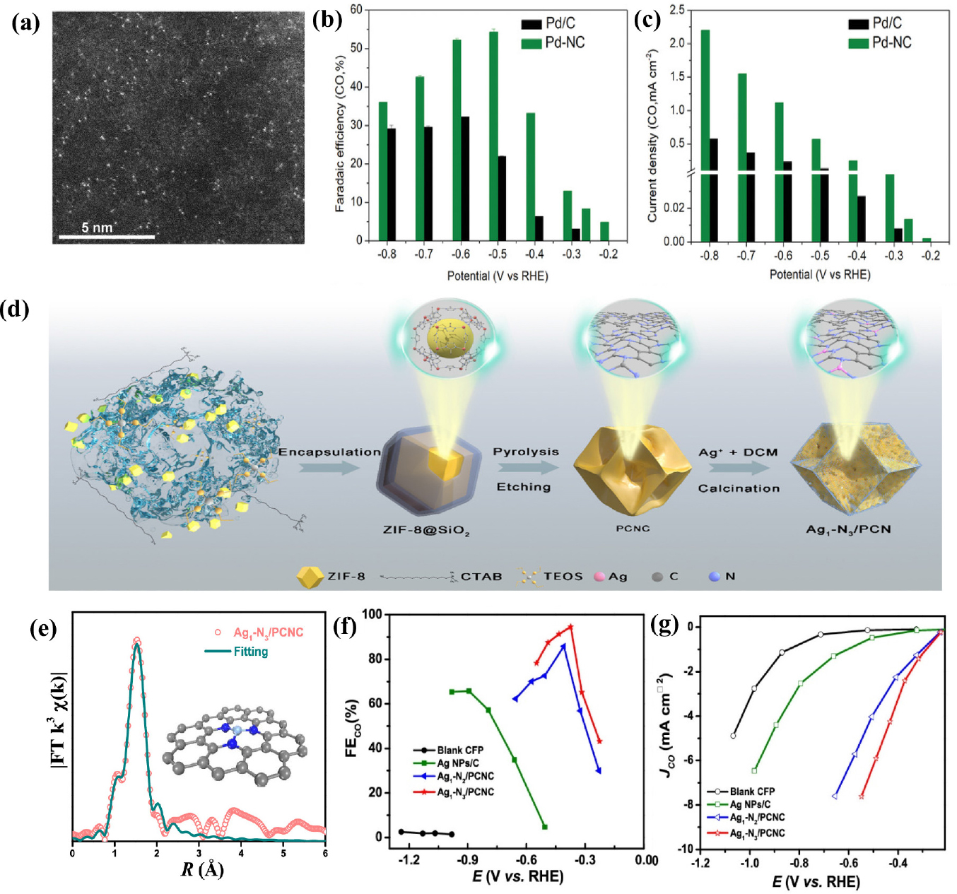
Fig. 3
(a) HAADF-STEM image of PD-NC (b) Faradaic efficiencies of CO at applied potentials. (c) Partial current densities of CO. Reproduced with the permission from Ref. (34) Copyright 2020, WILEY-VCH Verlag GmbH & Co. KGaA, Weinheim. (d) Schematic preparation process of Ag1-N3/PCNC. (e) EXAFS fitting curves of Ag1-N3/PCNC (f) FECO and (g) partial co current density at different applied potentials. Reproduced with the permission from Ref. (36) Copyright 2021, American Chemical Society.
3.2. Non-noble metal SACs
As an alternative to the use of precious metals, different transition-metal-doped nitrogenated carbon materials (M-N-Cs, M = Ni, Co, Fe, etc.), have attracted significant attention because of their relatively low cost and superior electrocatalytic performance for the conversion of CO2 to CO.23)
3.2.1. Ni-based SACs
Ni-based single-atom catalysts have been experimentally reported to exhibit outstanding performance for CO2RR, attracting a lot of interest. Li et al.44) demonstrated Ni SACs with Ni-N4 active sites using a topo-chemical transformation method [Fig. 4(a)], resulting in unprecedentedly high activity and selectivity for CO2 reduction. This strategy prevents Ni atoms from agglomerating to nanoparticles, providing abundant active sites, and consequently improving the CO2RR performance. The Ni-N4 sites exhibited excellent FECO over 90 % in the wide potential range from -0.5 to -0.9 V (vs. RHE) and reached a maximum FECO of 99 % at -0.81 V (vs. RHE) with a current density of 28.6 mA cm-2 [Fig. 4(b, c)]. In addition, DFT calculations indicated that atomically dispersed Ni-N4 reduced the reaction free energies needed for COOH* intermediate formation, promoting the formation of CO and thus leading to enhanced CO2RR activity. Carbon nanotubes (CNTs) have been widely used as supports for SACs preparation because of their high surface area, excellent chemical stability, and well-defined channel structure. Wu et al.45) constructed single-atomic Ni active sites in carbon nanotubes (Ni/N-CNTs) via the one-pot pyrolysis of a mixture of dicyandiamide, nickel acetylacetonate (Ni(acac)2) and Zn(NO3)2. The Zn source plays an important role in improving the nanotubular morphology, and increasing defect concentrations and active sites. The transmission electron microscopy (TEM) images of the Ni/N-CNTs confirmed the bamboo-like nanotubular structure of the catalyst and the aberration-corrected HAADF-STEM image further indicated many atomically dispersed Ni atoms throughout the entire structure. Ni/N-CNTs exhibit the maximum FECO of 98 % and TOF up to 304.5 h-1 at a relatively low potential of -0.65 V (vs. RHE) with the jCO of 5.3 mA cm-2. In addition, CO FE maintained over 80 % in a wide potential range of -0.57 to -0.81 V (vs. RHE), and also had good catalytic stability during a 20 h operation. Lu et al.46) introduced a simplistic way to synthesize single Ni sites encapsulated in N-doped carbon nanotubes (Ni SAs/NCNTs) by the pyrolysis of organic compounds (dicyandiamide and 2-methylimidazole) with Zn/Ni salts. With a high Ni loading of 6.63 wt%, the as-prepared Ni SAs/NCNTs showed exceptionally high CO2RR performance with a maximum FECO of 97 % at -0.9 V (vs. RHE) with a current density of 41.5 mA cm-2. In the process of synthesizing SACs, carbon black is extensively used as a carbon precursor because it is a commercially available and economical. In addition, carbon black has high-conductivity and a large surface area. Zheng et al.47) reported the synthesis of Ni SACs using commercial carbon black as a support via a facile and scalable approach. The optimized Ni SACs exhibited excellent CO2-to-CO performance with a FE of ~99 % at -0.681 V (vs. RHE) in a 0.5M KHCO3 aqueous electrolyte. When an anion membrane electrode assembly (MEA) was applied, the Ni SACs demonstrated high current densities above 100 mA cm-2 with ~100 % CO FE. Li et al.48) constructed Ni single atoms anchored on nitrogen-doped carbon (Ni/NC) by pyrolyzing nickel hexamine iodide, as the source of both Ni and N, and carbon black as the source of carbon. The presence of the Ni-N bonding configuration in X-ray photoelectron spectroscopy (XPS) indicated the formation of single Ni sites in the catalysts [Fig. 4(f)]. The Ni/NC showed remarkable CO FE of 92.3 %, outperforming metallic Ni catalysts. Zhang et al.49) synthesized the Ni/NC catalysts by high-temperature pyrolysis with different nitrogen precursors including polypyrrole, polyaniline, and polyacrylonitrile. Ni/NC_PAN_950 achieved highest FE of 96.5 % at -0.9 V (vs. RHE) [Fig. 4(i)], and current density of -12.6 mA cm-2 with TOF for CO formation of 4,760 h-1 at -1.2 V (vs. RHE). XPS [Fig. 4(g, h)] and X-ray absorption near-edge spectra (XANES), as well as electrochemical results emphasized that the pyrrolic N and Ni-N structures play a significant role in the excellent catalytic performance of Ni/NC. Carbon paper itself can also be used as a support, owing to its high electrical conductivity and mechanical strength. Li et al.50) reported a self-standing electrode containing single Ni atom by incorporating atomic Ni into a carbon paper. Ni SACs were successfully synthesized via consecutive acid activation, Ni adsorption, and pyrolysis steps. The optimized ACP/S-N-Ni exhibited CO selectivity of 91 % at -0.77 V (vs. RHE) with jCO of 3.40 mA cm-2 and FE was continuously maintained above 85 % in a broad potential range from -0.87 to -0.67 V (vs. RHE). Currently, two-dimensional carbon materials are attracting significant attention for the preparation of SACs owing to their large specific surface area, abundant active sites, and outstanding metallic conductivity. Liu et al.51) constructed a variety of M-N-C SACs with different transition metals for the CO2RR using layered montmorillonite (MMT) as the structural template and phenanthroline as the carbon-nitrogen precursor. Specifically, the Ni-SAC exhibited the most exclusive CO selectivity with the FECO exceeding 90 % in a wide potential range from -0.6 to -1.1 V (vs. RHE) and also excellent long-term stability for 30 h at -0.9 V (vs. RHE), retaining FE over 95 %. Furthermore, by comparing CO2RR activity with that of NC (nitrogen-doped carbon prepared with only MMT and phenanthroline), the importance of the transition metal Ni was emphasized. Ma et al.52) synthesized ultrathin Ni and N co-doped carbon nanosheets (Ni-N-CNSs) with uniformly dispersed nickel atoms using an in-situ pyrolytic strategy. Field emission scanning electron microscopy (FE-SEM) and high-resolution TEM images of Ni-N-CNSs indicated an ultrathin nanosheet structure. Benefiting from the advantages of porous structure, wide surface area, and rich mesopores, Ni-N-CNSs showed exceptional performance for CO2RR to CO with FE of 100 %, jCO of 121.4 mA cm-2, and stability over 25 h. DFT revealed that the Ni atoms provided appropriate electronic properties for the adsorption of CO2 and desorption of CO and restrained the competitive HER, enhancing the CO2RR activity. Jiang et al.53) dispersed isolated Ni single atoms into two-dimensional graphene nanosheets using the impregnation and reduction method, resulting in dramatically different catalytic behaviors from their bulk counterparts. Ni-NG demonstrated excellent CO selectivity of 95 % under an overpotential of 550 mV, and maintained unchanged upon 20 h of continuous operation. In addition, when an anion MEA is used, the catalyst shows better electrochemical performance such as remarkably high current density of more than 50 mA cm-2 with a TOF of 2.1 × 10⁵ h-1. DFT calculations suggest that the weaker CO binding and higher HER barrier result in the superior CO2RR performance of the Ni single atoms. Wang et al.54) constructed Ni-N-doped carbon-modified reduced graphene-oxide catalysts (Ni-N-C-rGo) using a coordination compound of Ni ions and dimethlglyoxime as a precursor to modify rGO. The optimized Ni-N-C-rGO catalyst exhibited high activity for the CO2RR to CO conversion with a current density of 10 mA cm-2, FECO of 85 % at -0.87 V (vs. RHE), and no deactivation for 10 h, suggesting promising catalyst for CO2RR [Fig. 5(a-c)]. Single Ni atom anchored on ultrathin porous N-doped carbon nanosheets55) were synthesized via a polydopamine-assisted g-C3N4 template method. The abundant Ni-N4 active sites and ultrahigh specific surface area of porous 2D supports (>1,000 m2 g-1) resulted in excellent CO2RR performance of NiSA/N-C with remarkably high FECO of 96 % at -0.86 V (vs. RHE), a current density of 26.4 mA cm-2 and highest TOF values of 20,752 h-1 at -0.84 V (vs. RHE). The following study focused on a using metal-organic framework (MOF) for SAC preparation. Zhao et al.56) successfully synthesized Ni SACs via ionic exchange of Zn nodes and adsorbed Ni salts [Fig. 5(d)]. The zeolitic imidazolate framework (ZIF-8) was synthesized in methanol at first and subsequently, as-synthesized ZIF-8 was dispersed in n-hexane, followed by the addition of an aqueous solution of Ni(NO3)2. Since Zn has relatively low boiling point, Zn atoms were selectively evaporated when ZIF-8 was calcinated at 1,000 °C, leaving the N-rich defects. These sites would be readily occupied by the Ni2+ ions and anchored by N coordination, forming isolated Ni single atoms. Ni SACs exhibited a TOF of 5,273 h-1, [Fig. 5(f)] with a FECO of over 71.9 % [Fig. 5(e)] and achieved a current density of 10.48 mA cm-2 at -0.9 V (vs. RHE). Ismail et al.57) reported the synthesis of Ni-N-C electrocatalysts by using ZIF-8 as a platform and investigated the influence of the Ni concentration impregnated into the ZIF-8 precursor in the CO2RR performance of single Ni atom catalysts. It was found that the increased Ni contents in the catalyst precursor resulted in the formation of Ni-based particles, shifting the selectivity toward HER rather than the CO2 RR. Ni-N-C with optimized contents of Ni reached a maximum CO FE of ~99 % at -0.68 V (vs. RHE) [Fig. 5(g, h)] with a current density of -2 mA cm-2. Yan et al.58) fabricated coordinatively unsaturated nickel-nitrogen (Ni-N) active sites embedded in porous carbon by high-temperature pyrolysis of Zn/Ni bimetallic ZIF-8. The Ni SACs showed high CO FE of 92.0~98.0 % over a wide potential window of -0.53 to -1.03 V (vs. RHE), the maximum current density of 71.5 ± 2.9 mA cm-2, and TOF of 10,087 ± 216 h-1 at -1.03 V (vs. RHE). DFT calculations indicated that coordinatively unsaturated Ni-N site promote CO2RR rather than HER, resulting in excellent performance in the CO2-to-CO conversion. Similarly, Ni-N doped porous interconnected carbon (NiNPIC) was prepared by calcinating the Zn-Ni bi-metal MOFs with different Zn/Ni proportions.59) The Ni loading of the NiNPIC was precisely controlled by changing the amount of Ni in the MOF precursors. The catalyst achieved CO FE of 95.1 %, current density of 10.2 mA cm-2, and outstanding stability at -0.54 V (vs. RHE). Such outstanding catalytic activity is mainly attributed to its interconnected porous structure as well as a large surface area with highly-accessible Ni-N active sites. Pan et al.60) reported single Ni atom coordinated with N confined in a carbon matrix derived from thermal activation Ni-doped doped ZIF-8 at 1,100 °C. Ni-N-C catalysts with atomically dispersed Ni atoms demonstrated enhanced CO2RR performance, with a maximum CO FE of 96 % at a low overpotential of 570 mV. Zhang et al.61) demonstrated a novel post-synthetic metal substitution strategy for fabricating single Ni atom catalysts coordinated with different N numbers on defective carbon supports derived from ZIF-8 [Fig. 6(a)]. Ni SACs coordinated by 3 nitrogen atom catalysts presented a high CO FE up to 95.6 % [Fig. 6(b)] with a TOF value of 1,425 h-1 at -0.65 V. Furthermore, DFT calculations revealed that the energy barrier of COOH* formation is reduced on the Ni-N3-C, thereby promoting CO2 reduction. Although the synthesis of SACs using MOFs has been steadily progressing, research is mainly limited to ZIF-8 involving abundant N. As N atoms are not involved in most MOFs, it is highly desirable to develop a novel approach for the construction of SACs based on non-nitrogenous MOFs. The host-guest cooperative protection strategy was used to synthesize Ni SAC, introducing polypyrrole into bimetallic MgNi-MOF-74.62) MOF-74 is a subclass of MOF with metal ion sites coordinated by a 2,5-dihydroxyterephthalic acid ligand. The introduction of Mg2+ extends the distance between adjacent Ni atoms, and polypyrrole serves as an N source for stabilizing the isolated Ni atoms during pyrolysis. Ni SACs with various N coordination numbers were prepared by controlling the pyrolysis temperature. Among them, NiSA-N2-C showed the highest selectivity towards CO with a high FE of 98 % [Fig. 6(c)], stability over 10 h and TOF of 1,622 h-1 at -0.8 V (vs. RHE) [Fig. 6(d)]. DFT calculations demonstrated that Ni SACs with lowest coordination number has the lowest free energy barrier for the RDS step and low energy low CO* desorption energy, resulting in superior CO2RR performance [Fig. 6(e)]. Adjusting the local environment and structure of the metal center is one of the strategies for promoting CO2RR performance. Rong et al.63) reported a simple strategy for synthesizing vacancy-controlled Ni single atoms (Ni-N3-V SAC) using precursors containing both nitrogen and oxygen with NiCl2 ‧ 6H2O. Both oxygen and nitrogen atoms in cyanuric acid and 2,4-diamino-6-phenyl-1,3,5-triazine lead to formation of Ni-N3O SACs, in which the oxygen atoms are removed under high temperatures owing to weak Ni-O interaction, generating a vacancy-defect Ni-N3-V SAC. Ni-N3-V SAC shows outstanding performance with FE over 90 %, CO2 reduction current density of 65 mA cm-2 along with unprecedented TOF value of 1.35 × 10⁵ h-1 at -0.9 V (vs. RHE) [Fig. 6(f-h)]. Chen et al.64) demonstrated a facile plasma-assisted and nitrogen vacancy (NV) induced coordinative reconstruction strategy to synthesize Ni single atoms (SA-NiNG-NV) for CO2-to-CO conversion. Raman spectra results indicated the presence of more defects in SA-NiNG-NV as the ratio of D-band intensity to G-band intensity for SA-NiNG-NV was higher than that for SA-NiNG [Fig. 7(a)]. This highly defective SA-NiNG-NV featured a high FECO of 96 % [Fig. 7(b)], jCO of 33 mA cm-2 and excellent long-term durability for 20 at -0.7 V (vs. RHE) [Fig. 7(c)]. Wang et al.65) synthesized single Ni atoms that were atomically dispersed on a carbon matrix consisting of Ni-N4 sites coordinated with an additional axial traction oxygen atom (Ni-N4-O/C). Owing to the additional oxygen atom which boosts the reaction kinetics of the CO2RR, the Ni-N4-O/C presented exceptional CO2RR activity with the highest FECO of 99.2 % at -0.9 V (vs. RHE) and a TOF of 11,187 h-1. Additionally, the CO2RR performances of Ni-N4-O/C are maintained over 90 % in a broad potential window ranging from -0.5 to -1.1 V (vs. RHE).
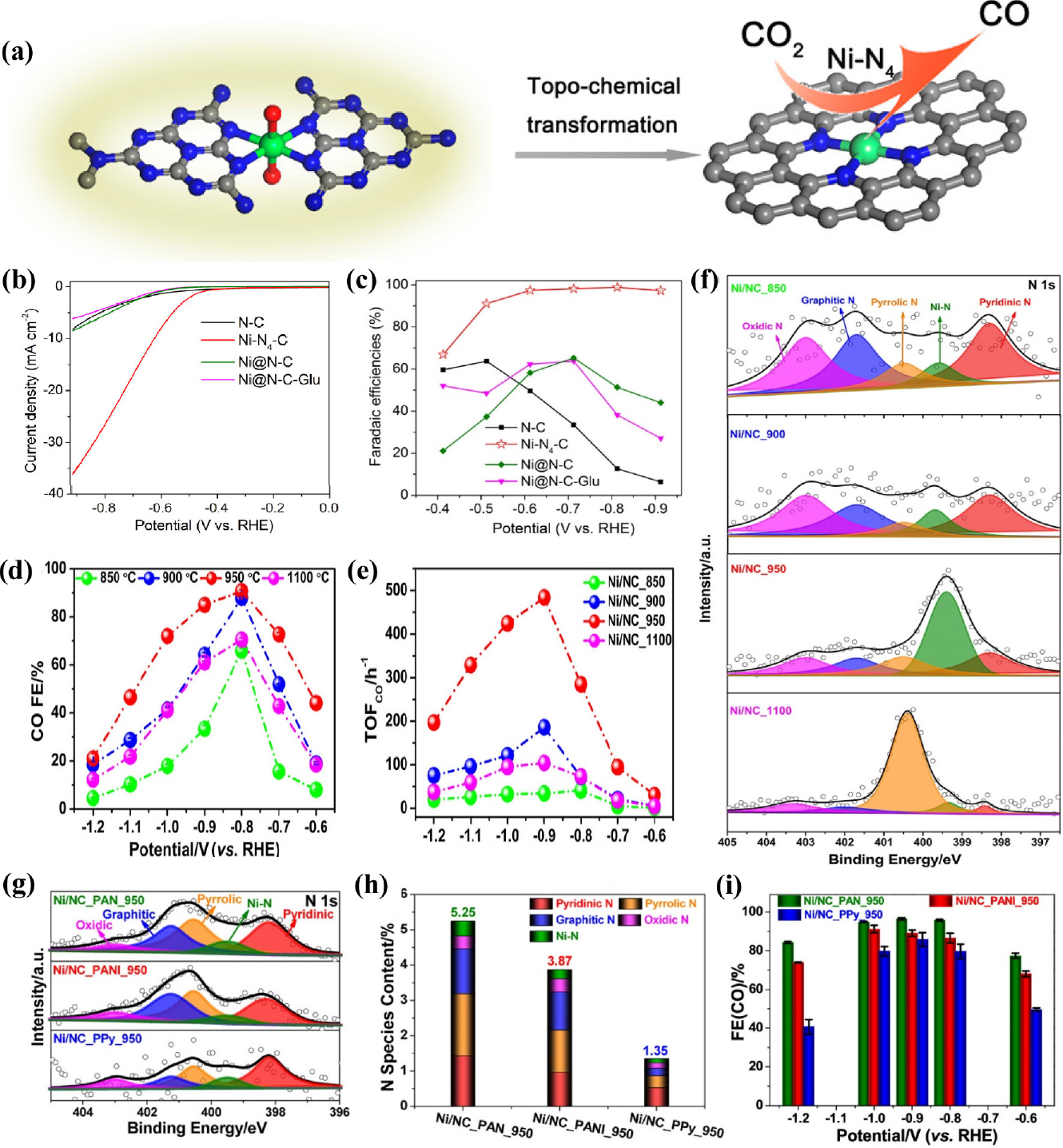
Fig. 4
(a) Scheme illustration of the synthesis of the Ni-N4-C catalyst (b) LSV and (c) Faradaic efficiencies of CO at different applied potentials on N-C, Ni-N4-C, Ni@N-C, and Ni@N-C-Glu electrocatalysts. Reproduced with the permission from Ref. (43) Copyright 2017, American Chemical Society. (d) CO FEs of Ni/NC_850, Ni/NC_900, Ni/NC_950, and Ni/NC_1100 within the potential window from -0.6 to -1.2 V. (e) TOFs of Ni/NC_850, Ni/NC_900, Ni/NC_950, and Ni/NC_1100 at different applied potentials. (f) N 1s XPS spectra of the Ni/NC obtained at different annealing temperatures. Reproduced with the permission from Ref. (47) Copyright 2019, American Chemical Society. (g) High-resolution N 1s XPS spectra (h) Atomic contents of N of Ni/NC_PAN_950, Ni/NC_PANI_950, and Ni/NC_PPy_950. (i) Faradaic efficiency for CO. Reproduced with the permission from Ref. (48) Copyright 2019, American Chemical Society.
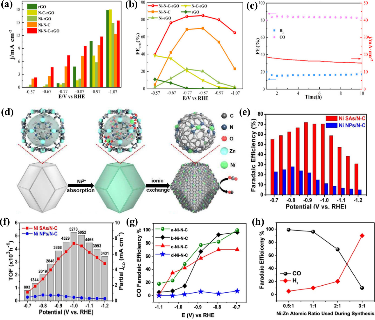
Fig. 5
Electrochemical performances of Ni SACs for CO2RR. (a) Current density and (b) FECO with different applied potentials. (c) Electrochemical stability test measured at -0.876 V (vs. RHE) for 10 h. Reproduced with the permission from Ref. (53) Copyright 2021, MDPI. (d) Scheme of the formation of Ni SAs/N-C (e) FEs of CO (f) Partial jCO and TOFs of Ni SAs/N-C and Ni NPs/N-C at different applied potentials. Reproduced with the permission from Ref. (55) Copyright 2017, American Chemical Society. (g) Faradaic efficiencies of CO on a-Ni-N-C, b-Ni-N-C, c-Ni-N-C, and d-Ni-N-C (h) Correlation between Ni/Zn atomic ratio and the produced CO and H2 at -0.68 V (vs. RHE). Reproduced with the permission from Ref. (56) 2022, American Chemical Society.
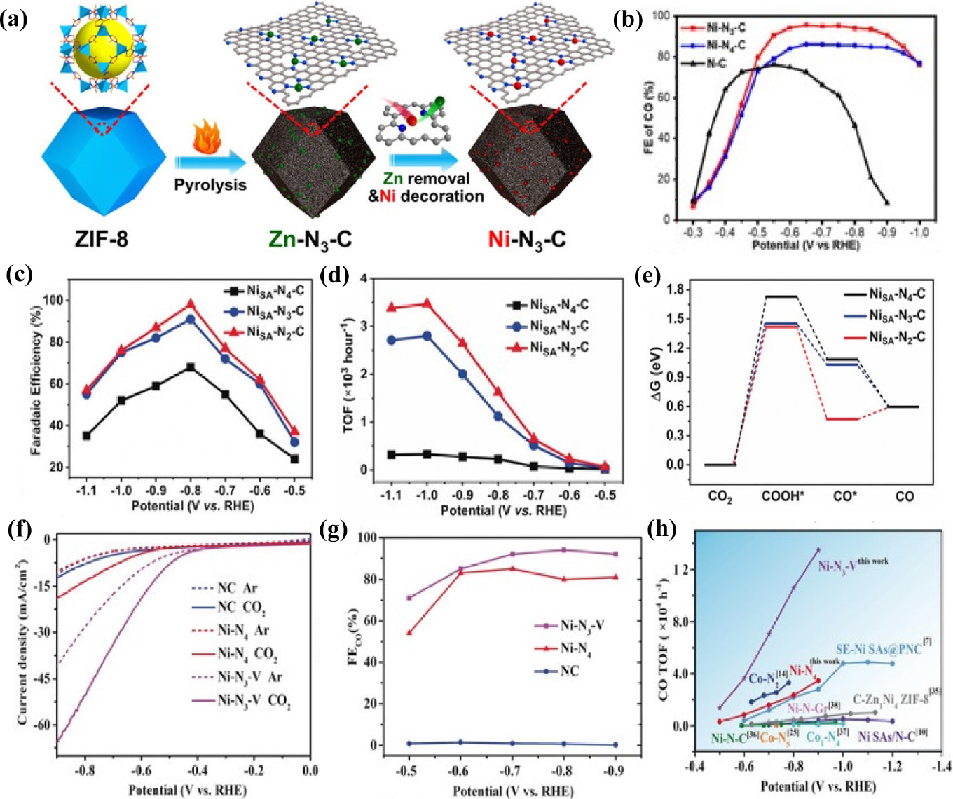
Fig. 6
(a) Schematic illustration of Ni-N3-C. (b) CO Faradaic efficiency of Ni-N2-C, Ni-N3-C, and N-C. Reproduced with the permission from Ref. (60) Copyright 2021, Wiley-VCH GmbH. (c) FEs of CO at different applied potentials (d) TOFs of CO production over NiSA-Nx-C. (e) Calculated free energy diagrams for CO2 electroreduction to CO on NiSA-Nx-C. Reproduced with the permission from Ref. (61) Copyright 2019, Wiley-VCH Verlag GmbH & Co. KGaA, Weinheim. (f) LSV curves in N2 or CO2-saturated 0.5M KHCO3 electrolyte for all different catalysts. (g) CO Faradaic efficiencies (h) CO TOF of Ni-N3-V and Ni-N4 compared with those of other SACs. Reproduced with the permission from Ref. (62) Copyright 2020, Wiley-VCH Verlag GmbH & Co. KGaA, Weinheim.
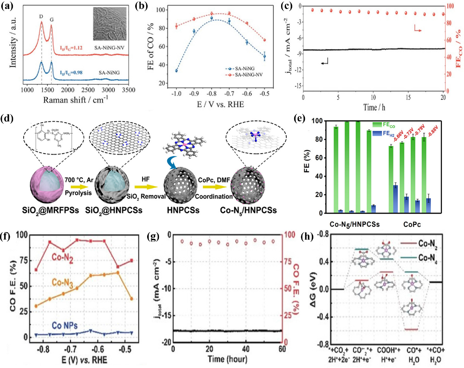
Fig. 7
(a) Raman spectra and (b) JCO of SA--NING-NV and SA-NING (c) Stability test of SA--NING-NV at -0.7 V (vs. RHE). Reproduced with the permission from Ref. (63) Copyright 2021, Wiley-VCH GmbH. (d) Synthesis strategy of Co-N5/HNPCSs (e) FECO and FEH2 of Co-N5/HNPCSs and CoPc. Reproduced with the permission from Ref. (65) Copyright 2018, American Chemical Society. (f) CO faradaic efficiencies at different applied potentials (g) Electrochemical stability test at -0.63 V (vs. RHE) during 60 h. (h) Free energy diagram of CO2RR over Co-N2 and Co-N4. Reproduced with the permission from Ref. (67) Copyright 2018, iley-VCH Verlag GmbH & Co. KGaA, Weinheim.
3.2.2. Co-based SACs
Atomically dispersed Co atoms have recently been studied because of their considerable performances in the CO2RR to CO. Compared with Ni-N-C and Fe-N-C SACs, Co-N-C generally displays relatively poor catalytic performance and more studies should be conducted to improve electrocatalyst performance. Pan et al.66) developed robust CO2RR electrocatalysts Co sites atomically dispersed on polymer-derived hollow N-doped porous carbon spheres (HNPCSs) [Fig. 7(d)]. Electrochemical measurements indicate that the HNPCSs demonstrate high activity and selectivity toward CO with FE above 90 % under a wide potential range from -0.57 to -0.88 V (vs. RHE) [Fig. 7(e)] because of its large surface are, abundant active sites and great electrical conductivity. The single-atomic Co-N5 site was found to be the active center for activating CO2, enabling rapid formation of key intermediate COOH*, and desorption of CO. Free-standing and 3D net-like single Co atoms decorated porous carbon membrane (CoSA/HCNFs)67) were synthesized via electrospinning. The FE-SEM image of the CoSA/HCNFs indicated that the randomly oriented carbon nanofibers form a 3D interconnected network structure. In addition, the N2 sorption isotherm of the CoSA/HCNFs confirmed the existence of both mesopores and macropores. The hierarchically porous structure of the CoSA/HCNFs facilitates large electrochemically-active surface areas, maximizing the exposure of single-atom cobalt sites. These self-supporting CoSA/HCNFs membranes exhibit FECO of 91 % and current density of 67 mA cm-2 in H-type cell, 92 % CO FE and 211 mA cm-2 current density in a flow cell, respectively. In a subsequent study, Wang et al.68) developed Co SACs via pyrolysis of a bimetallic Co/Zn ZIF. Three Co SACs with different Co-N numbers were selectively prepared at three different temperature (800, 900, and 1,000 °C) and named as Co-N4, Co-N3, and Co-N2, respectively. Electrochemical measurements demonstrated that Co SACs coordinated with two nitrogen atoms exhibited significant selectivity and activity toward CO production. Specifically, the catalyst achieved a maximum CO FE of 95 % at -0.68 V (vs. RHE) [Fig. 7(f)], jCO of 18.1 mA cm-2 at -0.63 V (vs. RHE) and excellent stability of over 60 h [Fig. 7(g)]. DFT calculations revealed that SACs with low coordination number show higher CO2RR catalytic activity due to rapid activation of CO2 to the CO2- intermediate [Fig. 7(h)].
3.2.3. Fe-based SACs
Fe-based SACs have recently demonstrated excellent performance for the CO2-to-CO conversion. Unlike other M-N-Cs, Fe SACs electrocatalysts exhibit the highest CO selectivity at lower onset potential. Ju et al.69) synthesized a family of M-N-C electrocatalysts containing catalytically active sites M-NX with bipyridine-based coordinated polymers and a variety of transition metals. As a result, Fe-N-C acted as a promising catalyst for CO2RR and reached FECO of 65 % at a smaller overpotential (VRHE = -0.55 V) than other electrocatalysts. In the following study, Fe3+-N-C electrocatalyst was prepared70) by pyrolysis of Fe-doped ZIF-8 under N2 at 900 °C. The as-prepared catalyst of atomically dispersed single-atom Fe sites produces CO at a low overpotential of 80 mV and jCO reaches 94 mA cm-2 with FECO exceeding 90 % at -0.45 V (vs. RHE). Operando X-ray absorption spectroscopy revealed that the active sites of the catalysts are Fe3+ ions, which are coordinated with pyrrolic nitrogen atoms and remain their oxidation state during CO2RR. The faster CO2 adsorption and weaker CO absorption at the Fe3+ center result in better performance of Fe3+-N-C compared with Fe2+-N-C. Pan et al.71) synthesized single-atom iron catalysts atomically dispersed on hierarchical CNT and graphene nanoribbon (GNR) networks (Fe-N/CNT@GNR) [Fig. 8(a)]. The unzipping of CNT leads to formation of GNR nanolayers attached to the outer walls of the CNTs, which play a significant role in anchoring the GNRs and hindering their aggregation. The mesoporous CNT@GNR architecture makes it possible to exhibit the best properties, including a high surface area and fast mass transport. Fe-N/CNT@GNR demonstrated the outstanding performance toward CO2RR, achieving a FECO of 96 % [Fig. 8(b)] with jCO of 22.6 mA cm-2 at -0.76 V (vs. RHE). Atomically dispersed axially coordinated Fe-N/CNT catalysts72) were also prepared via the introduction of animated carbon nanotubes. Through the axial coordination strategy, Fe TPP is uniformly dispersed on the surface of the animated carbon nanotube and the strong coordination between Fe atoms and N atoms hinders the agglomeration of Fe atoms during high temperature pyrolysis. The axial Fe-N/CNT displayed high electrocatalytic performance for CO with a FE of 95.47 % and stability for 10 h. The DFT calculation results revealed that axial Fe-N/CNT reduced the free energy required for CO* desorption, enhancing the CO selectivity. The following studies were devoted to fabricating Fe atoms via ZIF-8 assisted strategy for the CO2RR. Chen et al.73) established an effective strategy to synthesize Fe SACs (Fe-N5/Fe-N6) by tuning the coordination number of Fe with N by changing pyrolysis temperature. First, the Fe-doped ZIF-8 was synthesized through the typical synthetic method of ZIF-8, and then Fe-N5 and Fe-N6 were obtained by calcinating a Fe-ZIF-8 at 900 and 800 °C, respectively. The FECO for Fe-N5 exceeded 90 % over a broad potential window range ranging from -0.35 to -0.65 V (vs. RHE) with CO generation at lower overpotential. In addition, the TOF of Fe-N5 reached 5,006 h-1 at -1.05 V (vs. RHE), which is a very high value compared to the TOF value of Fe-N6 (1,324 h-1). DFT calculations indicated that Fe-N5 need lower free energy required for the formation of the key intermediate COOH*, leading to better CO2RR performance. Some studies have been dedicated to exposing abundant active sites on the surface support for high performance of the CO2RR. Ye et al.74) synthesized Fe SACs with isolated iron-nitrogen sites (C-AFC@ZIF-8) located on the carbon-matrix surface through functionalization of the ZIF-8 surface using ammonium ferric citrate (AFC). In comparison with C-AFC@ZIF-8 derived from bulk functionalization of ZIF-8 with AFC, C-AFC©ZIF-8 exhibits a much higher catalytic performances owing to its highly exposed Fe-N active sites on the surface. Specifically, the optimized electrocatalyst showed a maximum FECO of 93 % at -0.43 V (vs. RHE), and the maximum total current density of 23 mA cm-2 at -0.85 V (vs. RHE). Wu et al.75) reported atomically dispersed Fe atoms coordinated to N (Fe-Nx) within carbon nanorods (Fe-N-C) via high-temperature pyrolysis of a 3-dimensional sea urchin-like precursor. The physical characterizations result clearly confirmed that Fe was atomically dispersed in the catalyst and coordinated with N to form highly exposed Fe-N4 active sites. Benefiting from its porous structure with highly exposed active sites, as well as its large specific surface area, the Fe-N-C electrocatalyst presented a high FECO of 95 % at a small overpotential of 530 mV with jCO of 1.9 mA cm-2. 2D carbon materials such as graphene oxide, have been utilized as supports for anchoring Fe SACs. Zhang et al.76) successfully synthesized atomic iron dispersed on nitrogen-doped graphene (Fe/NG) by calcinating a mixture of GO and FeCl3 in an Ar/NH3 atmosphere at 700~800 °C. Fe/NG catalyst exhibited outstanding CO2RR performance toward CO with FE up to 80 %. HAADF-STEM, HRTEM, and EDS further revealed that Fe atoms are uniformly dispersed in the nitrogen-doped graphene. Recently, Zhu et al.77) developed a single Fe atom anchored on N-doped carbon nanosheets (Fe-SA/NCS-X) by directly pyrolyzing hemin-doped polyaniline. The Fe-SA/NCS annealed at 700 °C achieved FECO of 87 % at -0.45 V (vs. RHE), a low onset overpotential of 105 mV, and excellent stability over 10 h. DFT calculations revealed that the synergistic effect between graphitic N and the Fe-N4 active sites significantly lowered the free energy barriers of COOH* intermediate formation, thus promoting CO2 electroreduction to CO. Similarly, Zhang et al.78) developed a novel synthetic strategy for a single Fe atom electrocatalyst anchored on graphene using prolonged thermal pyrolysis of hemin and melamine. The as-prepared FeN5 catalyst showed remarkable catalytic performance with a maximum FECO of approximately 97 % at a very low overpotential of 0.35 V (vs. RHE) [Fig. 8(c)]. In addition, the jCO of FeN5 was significantly higher than that of the other catalysts [Fig. 8(d)]. The high CO2RR performance of FeN5 could be attributed to the additional axial ligand coordinated to FeN4. In contrast to FeN4, the axial pyrrolic N ligand depletes the electron density of the Fe 3D orbitals, resulting in rapid CO desorption for highly selective CO production [Fig. 8(e)]. Li et al.79) synthesized Fe SACs with FeN4 sites embedded on a carbon substrate (FeN4/C) via a confined pyrolysis strategy using Fe-doped graphitic carbon nitride template. A simple adsorption method was adopted to suppress the agglomeration of metal atoms during pyrolysis, providing abundant active sites for the CO2RR. The obtained FeN4/C SAC showed great stability over 24 h, maximum FECO of 93 % at -0.6 V (vs. RHE), and higher current density than that of other catalysts. Another Fe SAC with FeN4 sites was fabricated80) using Fe-containing and carbon-rich g-C3N4 (C-g-C3N4-Fe) as a single precursor. Abundant intrinsic defects play a key role in boosting the CO2RR performance of the as-prepared samples. The resulting catalyst demonstrated a FECO of 90 % and a CO partial current density of 33 mA cm-2, proving to be CO selective and highly active [Fig. 8(f, g)]. DFT calculations revealed that Fe-N4 with intrinsic defects exhibited a reduced energy barrier for CO2RR and suppressed the HER, inducing excellent electrocatalytic performance [Fig. 8(h)].
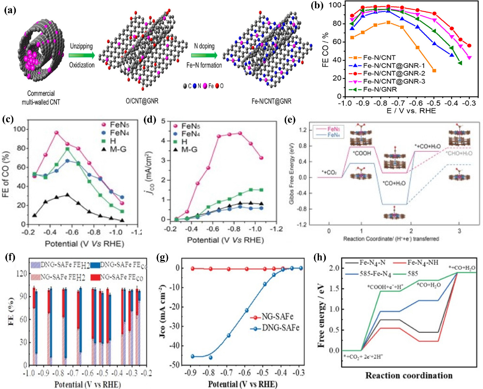
Fig. 8
(a) Scheme of the synthesis of Fe-N/CNT@GNR (b) CO Faradaic efficiencies. Reproduced with the permission from Ref. (70) Copyright 2020, American Chemical Society. (c) Faradaic efficiencies of FeN5, FeN4, H, and M-G for CO. (d) Partial current density for CO production on FeN5, FeN4, H, and M-G (e) Free energy diagram for electrochemical CO2 reduction to CO on FeN4 and FeN5, respectively. Reproduced with the permission from Ref. (77) Copyright 2019, Wiley-VCH Verlag GmbH & Co. KGaA, Weinheim. (f) Faradaic efficiencies of CO and (g) Partial CO current density plots at different applied potentials (h) Free energy diagram of CO2RR over Fe-N4-N, 585-Fe-N4, Fe-N4-NH, and 585 site. Reproduced with the permission from Ref. (79) Copyright 2020, Wiley-VCH GmbH.
3.2.4. Others
In addition to the above discussed M-N-C SACs (M = Ni, Fe, Co), some studies have been dedicated to other M-N-C catalysts for efficient CO2RR. The following study focuses on the synthesis of Zn-based SACs. Unlike other transition metals, there are relatively few studies on Zn-based SACs because of their low melting and boiling points, which make them evaporate easily during high- temperature pyrolysis.81) In addition, the active sites in catalysts containing isolated Zn atoms have not yet been identified accurately.82) Atomically dispersed single-atoms with Zn-N4 active sites could be easily obtained by pyrolyzing carbon black [BP 2000 (BP)] as the support, and, urea and zinc acetate as the N and Zn precursors, respectively.83) The atomic distribution of Zn was indicated through HAADF-STEM and nanoparticles or clusters were not found on ZnNX/C under HRTEM. A nitrogen-anchored Zn single-atom catalyst exhibited remarkable CO2 RR performance such as FECO as high as 95 % at -0.43 V (vs. RHE), over 75 h durability without decay of FECO, and high TOF up to 9,969 h-1 [Fig. 9(a-c)]. Recently, Li et al.84) synthesized nitrogen-stabilized low-valence Zn-based SAC (Znδ+-NC) consisting of both Zn-N4 and Zn-N3 sites by pyrolyzing a Zn-containing precursor (Zn-BTC) at 1,000 °C under Ar atmosphere in the presence of dicyandiamide (DCD). Zn-N3 sites lower the oxidation state of Zn owing to their electron-rich properties. DFT calculations reported that Zn-N3 sites reduced the energy barrier of COOH* intermediate formation, resulting in extraordinary CO2RR performance [Fig. 9(f)]. As-prepared mix-coordinated Zn SACs exhibited 99 % CO selectivity at a small overpotential of 310 mV [Fig. 9(e)] and current density of 1 A cm-2 was achieved using a flow-cell electrolyzer. In the following study, Ni et al.85) fabricated Sn SACs with a coordination structure of Sn-C2O2F by an indirect capturing route with a mixture of nano-tin oxide, polytetrafluoroethylene, and ZIF-8 [Fig. 9(g)]. Consequently, Sn SAC shows outstanding catalytic performance for CO2RR to CO with a maximum FE of up to 95.2 % and above 90 % in a wide potential window [Fig. 9(h)]. DFT calculations revealed that additional axial F coordination efficiently suppressed the competitive HER, promoting the conversion of CO2 to CO. Zhao et al.86) developed a Sn modified N-doped 3D porous carbon nanofiber catalyst through electrospinning and pyrolysis. Owing to their porous structure and atomically dispersed Sn sites, the as-prepared SACs exhibited high performance, reaching FECO up to 91 % at a low overpotential of 490 mV. Recently, Guao et al.87) prepared Sn SACs consisting of atomically dispersed SnN3O1 active sites anchored on an N-rich carbon matrix for efficient electrochemical CO2 to CO conversion. Unlike the conventional Sn-N4 configuration, asymmetric SnN3O1 configurations show outstanding CO2 to CO performance with a maximum FE of 94 %, CO partial current density of 13.9 mA cm-2 at -0.7 V (vs. RHE) and TOF of 23,340.5 h-1. DFT calculations showed that the unique SnN3O1 configuration reduced the activation energies of CO* and COOH* formation, facilitating CO formation. Yang et al.88) demonstrated a simple and scalable approach to fabricate a Cu SACs (Cu SAs/NC) via the one-pot pyrolysis of chitosan, KOH, and Cu salt. KOH act as the activation agent, creating large amounts of interconnected pores and channels, further facilitating electrolyte penetration. The atomically dispersed Cu-N4 active sites were verified by HAADF-STEM and XAFs measurements. The Cu SAs/NC catalyst demonstrates exceptional CO2RR activity and selectivity with a high FECO of 92 % at -0.7 V (vs. RHE) and high durability over 30 h. Zhang et al.89) synthesized Bi single-atoms catalysts with Bi-N4 sites anchored on porous carbon networks (Bi SAs/NC) through gas-migration/NH3-mediated strategy with bismuth-based MOF (Bi-MOF) and DCD. The optimized Bi SAs/NC exhibits high CO2 reduction activity, with a high FE of up to 97 % and TOF value of 5,535 h-1 at a low overpotential of 0.39 V (vs. RHE) [Fig. 10(a, b)]. Jia et al.90) reported Sb single atoms anchored on N-doped porous carbon for the first time. Single Sb atoms were synthesized by the simple pyrolysis of SbCl3 and urea on active carbon black in argon. Sn SACs showed a maximum CO FE of approximately 82.0 %, jCO of 2.4 mA cm-2 with a TOF of 16,600 h-1 at -0.9 V (vs. RHE). Despite the huge progress in SACs, they still struggle from structural simplicity and lack of active sites, which limits their further development. To solve this problem, diatomic site catalysts have emerged as alternatives to compensate for the drawbacks of SACs.91) Diatomic site catalysts (DASCs) have more active sites, and the synergistic effect of two adjacent atomic metals leads to enhanced catalytic activity while maintaining the unique characteristics of SACs.92,93) Cheng et al.94) synthesized diatomic catalysts (DACs) with N4Ni/CuN4 dual sites anchored on an N-rich carbon matrix using metal-organic frameworks. Ni/Cu-N-C presents an outstanding FECO of 99.2 % at -0.79 V (vs. RHE) and FE of over 95 % from -0.39 to -1.09 V (vs. RHE) as well as long-term durability of 60 h electrolysis. DFT calculations revealed that the synergistic effect between two adjacent Ni and Cu sites cause electronic redistribution, enhancing CO2 to CO performance. DACs with isolated Ni-Fe sites anchored on nitrogenated carbon were synthesized based on ZIF-895) [Fig. 10(c)]. HAADF-STEM revealed the presence of single Ni and Fe atoms that were atomically distributed throughout the catalysts. The catalyst achieved high selectivity toward CO with FE above 90 % under a wide potential range from -0.5 to -0.9 V (vs. RHE), reaching a maximum FE of 98 % [Fig. 10(d)] with jCO of 7.4 mA cm-2 at -0.7 V (vs. RHE). Similarly, another Ni-Fe diatomic catalysts96) with the advantages of both Ni and Fe based SACs were synthesized using a two-step process. First, Ni and Fe co-doped Zn-IRMOF-3 was prepared by one-pot solvothermal method and then, Ni/Fe-N-C catalysts were obtained by a high temperature treatment under an Ar atmosphere. The optimized Ni/Fe-N-C catalyst exhibited excellent performance for CO2 to CO reduction with FECO of 98 % at a low overpotential of 390 mV (vs. RHE). DFT results explain that diatomic Ni and Fe sites not only reduce the energy barrier of COOH* formation but also boost the desorption of CO*, leading to high CO2RR activity and selectivity. Recently,91) catalysts featuring dual-site iron anchored on a nitrogen-doped carbon matrix were prepared by Wang et al. Fe2-N-C DACs show lower energy needed for desorption of CO* intermediates, triggering CO2 to CO electroreduction. The FECO for Fe2-N-C exceed 80 % in a wide range of applied potential from -0.5 to -0.9 V (vs. RHE), TOF of 26,637 h-1, and jCO of -32.04 mA cm-2 [Fig. 10(e-g)].
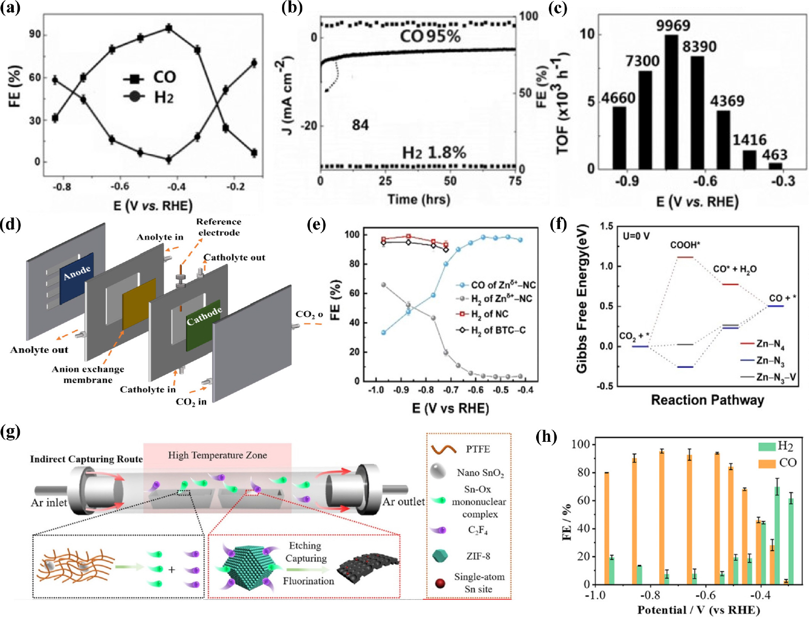
Fig. 9
(a) Faradaic efficiencies of CO and H2 On ZnNx/C. (b) Electrochemical stability test of ZnNx/C. at -0.43 V (vs. RHE). (c) TOFs of ZnNx/C Reproduced with the permission from Ref. (82) Copyright 2018, Wiley-VCH Verlag GmbH & Co. KGaA, Weinheim. (d) Schematic of a flow cell configuration. (e) FE of H2 and CO for Znδ+-NC, NC, and BTC-C. (f) Free energy diagram for electrochemical CO2 reduction to CO on Zn-N4, Zn-N3, and Zn-N3-V. Reproduced with the permission from Ref. (83) Copyright 2021, Wiley-VCH GmbH. (g) Schematic illustration of FNC-SnOF synthesis. (h) Faradaic efficiencies of CO and H2 on FNC-SnOF. Reproduced with the permission from Ref. (84) Copyright 2021, American Chemical Society.
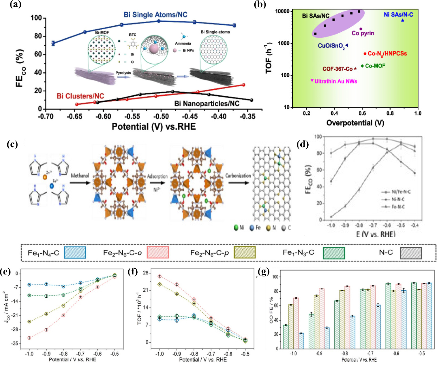
Fig. 10
(a) CO Faradaic efficiencies of Bi SAs/NC compared with Bi clusters/NC and Bi Nanoparticles/NC. (b) TOFs of BI SAs/NC compared with those of other SACs. Reproduced with the permission from Ref. (88) Copyright 2019, American Chemical Society. (c) Schematic of the preparation process of Ni/Fe -N-C. (d) CO Faradaic efficiency of Ni/Fe-N-C, Ni-N-C, Fe-N-C at various applied potential. Reproduced with the permission from Ref. (94) Copyright 2019, Wiley-VCH Verlag GmbH & Co. KGaA, Weinheim. (e) Partial CO current density (f) TOF and (g) FECO of Fe1-N4-C, Fe2-N6-C-o, Fe2-N6-C-p, and Fe1-N3-C catalyst. Reproduced with the permission from Ref. (90) Copyright 2022, American Chemical Society.
4. Conclusion
Recently, SACs have attracted enormous attention as alternative for the preparation of high-performance CO2RR electrocatalysts. SACs integrate the advantages of homogeneous and heterogeneous catalysts11,25,28) and exhibit many outstanding features such as maximum atom utilization, unique electronic structure, and exceptional performance. Although considerable research has been conducted on the development of various SACs to promote the electrochemical reduction of CO2, this research is still in its early stages. One of the key tasks to overcome is the low-mass loading of SACs, which affects large-scale applications. However, increasing the loading capacity causes agglomeration of nanoparticles during synthesis owing to high surface energy. Thus, the balance between the loading amount and the catalyst performance should be well controlled, and an appropriate support is needed to circumvent the possible aggregations and stabilize the SACs. Moreover, to enhance selectivity toward CO, it is crucial to optimize the binding energies of key intermediates by controlling the surface electronic structure of electrocatlaysts through defect engineering. Further research is required to develop SACs with extraordinary catalytic performance for practical applications.
