

1. Introduction
Now days, with developments in the industry, air conditions have become worse. The concentration of toxic gases in the atmosphere should be properly monitored. Among the toxic gases, ammonia(NH3) and hydrogen sulphide(H2S) cause a major hazard.1) The threshold limit for NH3 is given as 35 parts per million(ppm) for 8 h work shift and for H2S, Occupational Safety and Health Administration limit is 20 ppm for a period of 15 min short-term exposure limit.2) Various physical, physicochemical, and biological upgrading technologies have been developed to separately or simultaneously remove NH3 and H2S.3) For example, water scrubbing, which is a dominant technique in biogas upgrading, is a relatively simple and inexpensive process where both NH3 and H2S are able to diffuse into pressurized water. However, issues can occur when simultaneously removing H2S and NH3 due to the accumulation of sulfur, causing fouling and clogging of pipework; therefore, it is beneficial to remove H2S beforehand using a separate removal technique.4) This infers higher capital, operational and maintenance costs to the project, thus decreasing the applicability of biogas upgrading on dairy digesters.
Activated carbons(AC) can be produced from a variety of widely available precursor materials, such as coal, wood and many other manufactured polymeric materials (e.g. phenolic resins). One superior advantage of using synthetic polymers is that the chemical composition, morphology and pore structures of the resulting carbon materials can be better controlled relative to the use of other feedstock (e.g. coal). For instance, investigations conducted by Lu’s group demonstrated the feasibility of using polymers to produce monolith AC adsorbents, and one of the prepared nitrogen-enriched carbon monolith shows a toxic gas adsorption capacity as high as 3.13 mmol/g (13.77 wt%) at 25 °C and ambient pressure.5) However, most of these carbon-based adsorbent materials are produced by using costly sophisticated processes, which may prove difficult and uneconomic to scale up. Further, they are often produced in fine powder forms, which are not ideal for use in solid looping processes where fluidized and/or moving bed reactors are most likely to use. In this study the feasibility of using a novel commercialized hydrothermal process to produce functioning spherical AC adsorbent materials for carbon capture has been investigated, and a number of AC adsorbents with different textural and chemical properties have been evaluated in terms of their toxic gas adsorption performances at both ambient and elevated pressures. These AC adsorbents possess desirable spherical shape, high mechanical strength and low dusting properties, which are the ideal characteristics for fluidized bed looping applications.6-8)
Zeolites are one of the most important materials in the fields of petrochemical and fine chemicals because of their strong acidity, high surface area, resistance to high temperatures, and a regular pore structure 0.4-0.8 nm in diameter, which is close to the molecular size of hydrocarbons. 9-12) Zeolites are highly cationic and favor adsorption of the molecule with high quadruple moment. In the case of adsorbent with a-polar surface like ACs, it favors adsorption for molecules with high value of polarizability. 13-15)
Combination of activated carbon and zeolite may bring their respective adsorption characteristics and advantages into full play. Nevertheless, combination of activated carbon and zeolite involves in their respective efficient adsorption MW range, and it needs to be quantified. Possible alteration of effluent quality which results from dosing both activated carbon and zeolite in coagulation process is also still indeterminate. Additionally, ascribe to the potential complicated chemical mechanism and dynamic conditions different dosing points of activated carbon or zeolite in treatment process may have various influences on the final effluent quality. To our knowledge, research about these issues still remain lacking.
In this study, activated carbon(coal based activated carbon parched from Dae-Jung Chemical and Metals Co. Ltd Korea) as carbon source was used to prepare spherical carbons containing zeolites through the shape/ activation process. The physicochemical characteristics of the spherical carbon samples were measured and a gas adsorption test of NH3 and H2S was carried out.
2. Experimental Procedure
2.1 Materials and reagents
The activated carbon(Dae-Jung Chemical and Metals Co. Ltd Korea) and zeolite(Dae-Jung Chemical and Metals Co. Ltd Korea) were used for the preparation of the AZP samples. Phenolic resin sucrose and starch was used as a bonding agent, and was purchased from Kangnam Chemical Co., Ltd(Korea). Alcohol(95 %) was used as a dispersing agent, and was purchased from Samchun Pure Chemical Co., Ltd(Korea). For preparing and forming the spherical carbons, a shaped mould, shaker sieve and shaker were used, which we made ourselves. NH3 and H2S were purchased from Samchun Pure Chemical Co., Ltd(Korea). The appearances of these machines were recorded in detail in our previous studies.16-17)
2.2 Preparation of spherical carbons containing zeolite(AZP)
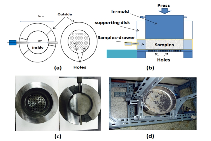
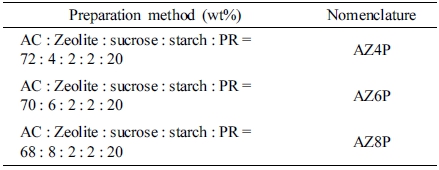
The manufacturing process and nomenclature of the AZP are shown in Fig. 1 and Table 1, respectively. The method of AZP production includes two steps: formation and activation. First, AC, zeolite, sucrose, starch and PR were mixed with different weight ratios: 72: 4: 2: 2: 20, 70: 6: 2: 2: 20 and 68: 8: 2: 2: 20, respectively. The premixes were added into alcohol (20 % ~ 30 %). The mixture was then put into the shaped mold to form agglomerates; a shaker and a sieve with size 30~60 mesh was used with a shaking rate of 50 round/min and heating at 80~90 °C. After shaking for 10 min, the agglomerates formed spheres and dried at 200 °C. Then, the spherical agglomerates were heated with CO2 at a flow rate of 150 mL/min at about 800 °C for 2 h with a heating rate of 10 °C/min to form AZP.
2.3 Strength measurement
Strength measurement was determined based on JIS R 7212 by using one-point bending(Instron 4201) with a support distance of 30 mm/min and cross head speed of 0.5 mm/min. The diameter size of sample was about 5 mm, and the strength density was calculated by the following equation:
Where σF is strength density(kg/m2), P is breaking load (kg), L is support distance(cm), B is width of sample (cm) and D is thickness of sample(cm).
2.4 Removal of H2S and NH3
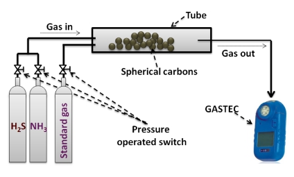
The H2S and NH3 adsorption amount has been measured by comparing the chemical and physical adsorption amount. In addition, the removal of hydrogen sulphide generally used measurement by detecting tube method. Passing a constant concentration of the standard of harmful gases in Column adsorbent is filled in a fixed bed adsorption force measurement experiments adsorbed by the adsorbent and to GASTEC use in the gas outlet periodically(Japan), etc. produced, standard gas detecting tube of the gas type measuring range which is sold (examples: 4 L is hydrogen sulfide 1-240 ppm, 3 M is seeking a breakthrough point by measuring the concentration of ammonia 10-1000 ppm measurable), and in relation to detecting tube configuration is defined by JIS test method. A typical harmful gases adsorption process is shown in Fig. 2.
2.5 Characterization
The crystal structures and phases of the AZP samples were obtained by XRD(Shimata XD-D1, Japan) with Cu Kα aradiation (λ = 1.54056) in the range of 2θ from 10 to 80° at a scan speed of 1.20 m−1. Energy dispersive Xray spectroscopy(EDX) was also employed for elemental analysis. The surface morphology and structure of the SCCT was examined in an SEM(JSM-5200, JEOL, Japan). The BET surface area by N2 adsorption method was measured at 77 K using a BET analyzer(Monosorb, USA).
3. Result and Discussion
3.1 Structure and morphology
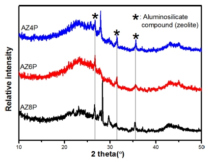
Fig. 3 shows the XRD patterns of prepared spherical AZP samples. Specifically, the zeolite skeleton is basically retained showing those main characteristic peaks at 22.5- 25°, 30° and 40° were in good agreement with the orthorhombic phase of ZSM-5 zeolite,18-20) the typical characteristic peaks of SiO2 and Al2O3 appear at 22.5° and 32- 45o, respectively.21-22) The intensity of peak for SiO2 and Al2O3 in sample AZ6P inhibits higher than that of AZ4P and AZ8P, which can be speculated that the amount of zeolite used in AZ6P is relatively appropriate. According to the previous studies, the appropriate amount of zeolite used in composite materials will exhibit excellent gas removal activity.23-25)
For elemental analysis of AZP samples(AZ4P, AZ6P and AZ8P), these samples were analyzed by EDX. The EDX spectra of AZP samples are shown in Fig. 4. The spectra showed the main elements as presence of Ka, Ca, O, Al and Si with strong C peak. O, Al and Si were conrmed as main componential elements from SiO2 and Al2O3 in zeolite. These results indicated that after carbonization and activation at high temperature, the composite of zeolite-SACs did not be destroyed due to the excellent thermal and hydrothermal stability of zeolite.26)
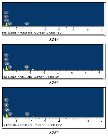
Fig. 5 shows SEM images of AZP samples(AZ4P, AZ6P and AZ8P), respectively. It can be seen that the hollow channels of carbons were interrupted by mixing with binder agent. And because zeolite particulates are uniformly dispersed over the activated carbons, no obvious aggregation of zeolite particle was found. Because all most AC powder was agglomerated together, thus forms a lot of bulks inside of the sphere sample. With increasing the amount of zeolite and decreasing the amount of AC, the morphology of prepared spherical sample become better shown in Fig. 5b. It can be indicated that the excellent adsorption property of zeolite and AC, promote adsorption binder materials in the mixing process thus inhibit better morphology. However, when the amount of zeolite was increased to 8 % in AZ8P, the similar result can be observed compared with sample AZ4P, larger bulks have generated shown in Fig. 5c. As a result, the specific surface area of AZ4P, AZ6P and AZ8P was detected as 1206 m2/g, 1015 m2/g and 940 m2/ g, which was in agreement with SEM results.
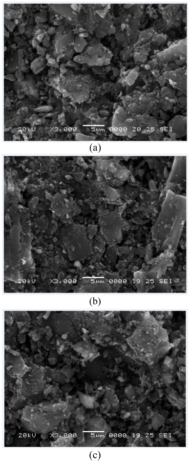
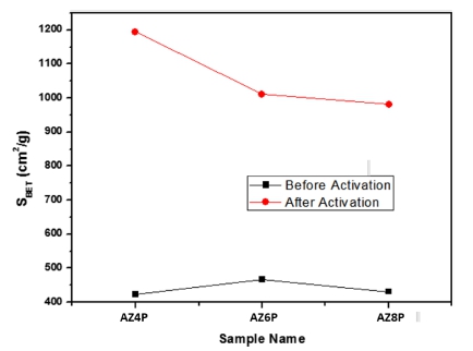
Fig. 6 shows the changes of BET surface area of AZP samples before and after activation. It is clearly seen that these surface areas were decreased with the increasing amount of zeolite before activation.27) However, AZ6P showed the highest specific surface area after activation, but AZ4P and AZ8P almost have the same specific surface area. Similar results have been reported by Kuwahara and Yamashita.28-31)
3.2 Strength and ignition temperature of AZP samples
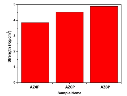
Fig. 7 shows the strength values of AZP samples after activation. As shown in Fig. 7, addition of zeolite can increase the strength value of carbon to a certain extent. The Strength of AZ4P, AZ6P and AZ8P was detected as 3.5 kg/cm2, 4.5 kg/cm2, 4.9 kg/cm2. This indicated that the zeolite has a significant influence on the strength of AZP samples. It was determined that the strength values of spherical activated carbon are increased with an increasing amount of zeolite. This may due to the exhibit more excellent stability and strength.32) The ignitions of AZP samples after activation are 456 °C, 560 °C and 589 °C respectively. It is obviously that AZ8P has the highest ignition temperature at about 589 °C. This illustrated that add more amount of zeolite in the sample£¨Because zeolite has better thermal stability and heat resistance. To some extent, improve the heat resistance of the samples after binding with AC.33)
3.3 Removal of H2S and NH3
Fig. 8 shows the adsorption of H2S as a function time in the presence of different AZ4P, AZ6P and AZ8P sample after activation, respectively. The order of the H2S adsorption ability was as follows: AZ8P > AZ6P > ATP4, zeolite structures exhibit relevant physicochemical properties over other adsorbents such as activated carbon,34) so that increase the content of zeolite in the sample, improved its adsorption capacity of hydrogen sulfide. Activated carbon has the microporosity with some kinds of functional groups, and then zeolite has some kinds of metallic components with small pore size. The sorption properties seem to be strongly dependent on the degree of sorbent microporosity and pore structure. And, small pore size, large surface area and basic surface functional groups play an important role in the adsorption of acidic gas molecules. Sitthikhankaew et al.35) showed that oxygen in the gas(O2/H2S = 7) may extend the time until breakthrough by up to 16 times, at a gas humidity of 70 % by even 30 times. Xiao et al.36) could also demonstrate this behavior. Removal of H2S is a required process because it leads to corrosion in transport lines and poisoning of many catalysts even in low levels.
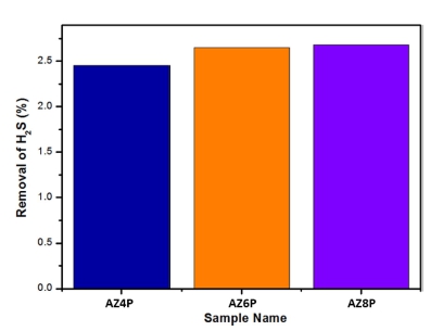
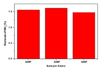
Fig. 9 shows the adsorption of NH3 as a function time in the presence of different AZ4P, AZ6P and AZ8P sample. Complete removal of NH4+ is required due to its toxicity to the majority of aquatic life. For example, the ammonium nitrogen concentration for most fish species must not exceed 1.5 mg NH4+ ion.37-38) NH4+ concentration, in certain surface waters serving as a source of potable water, is much higher than the permissible level, due to large quantities of industrial and municipal wastewater being discharged into existing water resources. 39) This threatens the availability of safe drinking water and, thus, human health. For this reason, the prevention of nitrogen pollution with NH4+ removal from wastewater is of great importance.40-41) The NH3 adsorption result was as follows: AZ6P > AZ4P > AZ8P, this showed that AZ6P(AC: zeolite: sucrose: starch: PR = 70: 6: 2: 2: 20) sample had the most suitable proportion, nearly 1.65 percent of NH3 removed by AZ6P sample. This may attribute to the highest specific surface area after activation among these samples which was shown in the previous BET analysis in Fig. 6.
4. Conclusion
Spherical carbons containing zeolite, which were uniformly dispersed on the activate carbon according to the result of SEM image. Through the results of BET surface area evaluation, the AZ6P sample was found to have the highest specific surface area after activation. The chemical compositions of the AZP samples were characterized by XRD and EDX, which showed carbon and zeolite as major components in the AZP samples. According to the compressive strength and ignition test, AZ8P sample had the best hardness and highest temperature resistance capacity. After activation AZ8P sample had the best H2S adsorption capacity, AZ6P was the most suitable for the adsorption of ammonia.
