

1. Introduction
2. Literature Survey
3. Viscoelastic Autoclave Bonding with Tapered Epoxy Reinforcement Polyurethane Films
3.1. Viscoelastic autoclave spunbond interlayer bonding
3.2. Tapered epoxy polyurethane reinforcement adhesives film
3.3. Scientific hypothesis
4. Result and Discussion
4.1. Experimental setup
4.2. Performance metrics of the proposed model
4.3. Comparison of proposed model with previous models
5. Conclusion
1. Introduction
Composite sandwich structures have garnered substantial attention within numerous engineering applications, due to their capacity to serve as advantageous substitutes for traditional construction materials. This is attributed to their distinctive mechanical characteristics, including exceptional specific flexural stiffness, remarkably low structural weight, and outstanding resistance to flammability and corrosion. The sandwich structure’s design incorporates stiffer materials for the cover plate and softer materials for the core plate, resulting in superior properties compared to conventional structures. In this configuration, the face sheets play a pivotal role in bearing in-plane flexural and compression loads, while the thicker core layer effectively distributes shear loads.1,2,3,4)
Numerous studies have shown that the construction needs for more durable and economical infrastructures could be achieved by using composite sandwich structures. In current studies, orthotropic composite materials like carbon fiber and glass fiber-reinforced plastic are used in the upper and lower plates of a sandwich structure. Viscoelastic materials like rubber, aluminum, polymeric foam, honeycomb, lattice truss, and corrugated patterns are the most commonly used cores.5,6,7) Due to the susceptibility to humidity, foam cores are not advised for use in aviation applications. The porous honeycomb is the core that received most of the attention from analytical, numerical, and experimental research areas. Other possible advantages of this construction include thermal insulation, shock absorption, radar absorption, corrosion resistance, and exceptional resistance. The complicated behavior of honeycomb panels, including stress concentration and buckling, is studied using a finite element technique (FEM) with reasonably high accuracy. Building an accurate material model using this process takes more time since it considers the structure’s complicated nature and its many different factors, especially during the early design and optimization stages.8,9,10)
The total effectiveness of sandwich constructions is not just affected by the properties of the facing but further influenced by the qualities of the core, the adhesive bonding of the core to the skins, and the geometrical dimensions. Sandwich beams exhibit a variety of failure modes when subjected to general bending, shear, and in-plane loads. The constituent material overall gets affected by the qualities, shape, and loading kind of how they start, spread, and interact. By doing a complete stress analysis and using the right failure criteria in the important areas of the beam, failure modes and their onset may be predicted.11,12) The component materials’ nonlinear and inelastic nature as well as the intricate relationships between the failure modes have made this study challenging.
An analytical model based on the complex modulus technique, the polynomial expansion approach, and the enhanced Rayleigh-Ritz method is suggested to examine the free vibration and damping properties of a highly integrated sandwich structure. Every construction of sandwich composite structure must undergo a vibration, bending, and buckling study to be used practically and to perform better. Every system also has a range of permitted stiffness, strength, and natural frequency; catastrophic failure (sudden failure) occurs when the permitted limit is surpassed.13,14) Even with more advancements in the composite sandwich beam, there are still many improvements required for better load-carrying capacity and to increase the life span of the beam by eliminating the delamination failure, avoiding buckling and local deformations in the beam, and further limitations in the present research. Major contributions in this paper are given as follows.
• During compression face wrinkling, existing approaches formation of micro cracks between the face layers, and shear stresses exceed the interlaminar bond strength, which leads to interlaminar delamination failure in the beam which is solved by compliant interlayers (viscoelastic polymers combined with spunbond nonwovens fabrics) avoids the formation of micro cracks and autoclave bonding improves the interlaminar bond strength.
• The existing special reinforcement methods create buckling and local deformations on the core material and it directly affects the stiffness of the beam, so a novel tapered core reinforcement and epoxy polyurethane adhesive avoids buckling and local deformations and improves the stiffness of the beam.
These contributions mentioned above have been considered for solving the problems in the composite sandwich beam in the existing methods. The content of the paper is organized as section 2 describes the literature survey, section 3 describes the proposed methodology and its working process, section 4 discusses the proposed model evaluation, performance, and comparative analysis, and section 5 concludes the paper.
2. Literature Survey
Zhou et al.15) examined how the temperature affects the bending characteristics at three points and the methods by which carbon fiber composite sandwich beams with Y-frame cores fail. The composite sandwich beams with Y-frame cores were first made using the hot-press technique. The impact of temperature on the failure mechanism, bending failure load, and load-displacement curves was then examined. Bending failure loads decrease with increasing temperature, with significant variations between low and high-temperature ranges. The study’s drawbacks are a focus on carbon fiber composite sandwich beams with Y-frame cores, which limits its applicability to other structures and does not consider the combined effects of temperature and moisture, which have a different impact on bending properties and failure processes.
Mansourinik and Taheri-Behrooz16) analyzed the behavior of sandwich beams with initial core-skin debonding under flexural pressures, taking advantage of different beam lengths and composite skin layups. Sandwich beams were created using two distinct composite skin layups [0/90]2 and [45/-45]2 and three different lengths 100, 180, and 280 mm. During the fabrication of the defective sandwich beams, a preliminary artificial debonding was produced between the core and face sheets. Core-skin debonding on the compression side greatly impacted loading capacity, whereas the cohesive zone model and extended finite element method successfully captured crack initiation and propagation. Specific layup sequences and beam lengths restrict the results’ applicability to other configurations.
Zhang et al.17) developed a unique technique to enhance hybrid composite sandwich beam performance using carbon fiber-reinforced polymer (CFRP) face sheets and aluminum foam core, examining deformation and failure under quasi-static stress and low-velocity impact. Indentation, face-sheet fracture, core shear, and core shear-tension are the four active failure modes that hybrid composite sandwich beams display, according to the experimental data. Advantages of this technique include improved structural integrity, enhanced load-carrying capacity, and potentially reduced mass compared to uniform thickness configurations. Limitations include differences in low-velocity impact collapse loads from theoretical predictions, suggesting that advanced analytical models are required to accurately predict dynamic behavior.
Wei et al.18) analyzed the three-dimensional failure mechanism map and three-point bending tests, to determine the bending properties of all-composite honeycomb sandwich beams. Six different failure modes were considered when building the map using analytical models: intracellular dimpling, face fracture, core indentation, shear buckling, shear fracture, and debonding. A three-dimensional failure mechanism map was created to describe the main failure mechanism. Three-point bending experiments on sandwich beams with various core relative densities, face thicknesses, and loading spans were performed to validate the analytical models and three-dimensional failure mechanism map. Identification of optimal load-weight ratios and paths for various geometrical parameters enhances design precision. The three-dimensional failure mechanism map does not show core indentation, which was not seen in the trials.
Selvaraj et al.19) studied the dynamic responses of a double-core sandwich composite beam using both experimental and computational techniques. Because of its higher natural frequency values, this technique improved its single-core competitors in terms of stiffness qualities and dynamic behavior. The stiffness of double-core sandwich composite beams was greatly affected by fiber angle orientations, thickness ratios, and aspect ratios, according to parametric research. The use of two viscoelastic layers is an important aspect of increasing structural stiffness. Due to restrictions in the manufacture of sandwich beams, the results varied.
Zhang et al.20) created a novel steel-concrete-steel (SCS) sandwich beam using hybrid shear connections made of overlapped headed studs and J-hooks. This study tests eight SCS sandwich beams with various shear span-to-depth ratios, steel contribution ratios, kinds of shear connectors, and spacing of shear connectors to explore the effects of the degree of composite action and the mechanism of such sandwich beams. The study showed that the type and spacing of shear connections had an inverse impact on shear resistance when compared to the λ ratio. But there is an obstacle in precisely measuring bond-slip effects and identifying the best parameters in every scenario, so more study is needed to achieve extensive optimization.
Madenci et al.21) proposed a precise mixed zigzag theory (HZZTM) for the free vibration analysis of sandwich plates and laminated composites. The proposed zigzag theory’s in-plane displacements, which concur with three-dimensional analysis, demonstrate an abrupt discontinuity in slope at interfaces and a nonlinear distribution through thickness. A preprocessing strategy based on the three-dimensional (3D) equilibrium equations and the Reissner mixed variational theorem (RMVT) is utilized to determine the precise transverse shear stresses. The higher-order theories are unable to accurately predict the natural frequencies of soft-core sandwich plates.
Kallannavar and Kattimani22) examined the free vibration analysis of sandwich plates and laminated composites. Shell elements for composite plates and solid shell elements for sandwich plates are used in the development of the finite element model in the ANSYS parametric design language (APDL) tool. Aluminum core and graphite-epoxy face sheets were used to model sandwich structures. For the analysis, bending stiff [0°/0°/30°/-30°]s, torsion stiff [45°/-45°/-45°/45°]s, and quasi-isotropic [0°/45°/-45°/90°]s fiber orientations are taken into account. In laminated composite plates, the quasi-isotropic layer configuration had greater natural frequencies for lower modes, whereas the torsion rigid fiber orientation had higher natural frequencies for higher modes. Due to the anisotropic and nonlinear properties of composite materials, which result in errors in the prediction of natural frequencies and mode shapes, modeling their behavior effectively was difficult.
Kashani and Hashemi23) utilized both the conventional finite element method (FEM) and dynamic finite element (DFE) methods, bending-torsion coupled free vibration analysis of prestressed, layered composite beams exposed to axial force and end moment. The coupled differential equations of motion were transformed using a polynomial interpolation function in the finite element approach, and then the weighted residual method of the Galerkin type was used to solve the discrete issue. Trigonometric shape functions were used to implement the equations in the dynamic finite element method as nodal displacement descriptions. Meshing errors led to inaccuracies in the solution. Meshing errors have led to inaccurate solutions because the quality of the mesh used to discretize the domain impacts the accuracy and convergence of the Galerkin procedure.
Wang et al.24) proposed a two-dimensional elasticity model for laminated graphene-reinforced composite (GRC) beams, under the assumption of the plane-stress condition in each layer. Although, presumably, graphene disperses equally throughout each layer, the volume percentage of graphene varies from layer to layer. The governing partial differential equations and boundary conditions are directly derived from the two-dimensional elasticity theory for any given individual layer. To ensure correctness and efficiency, state-space equations for individual layers were obtained using the multi-term Kantorovich-Galerkin method (MTKGM). Using the transfer matrix method, interface displacement, and stress continuity conditions create a global equation that reduced computational complexity because total variables were independent of the number of layers. There are variations in the graphene distribution patterns across the thickness due to the variations in the graphene volume fractions between the layers.
Shah et al.25) proposed an innovative method that combined a 3D-printed CFRP top face sheet with a GFRP core in a hybrid arrangement to improve the bending performance of corrugated sandwich composite structures (SCS). The corrugated SCS with square core geometry outperformed because of its vertical walls and wide bonding area. The hybrid SCSs with a CFRP core experienced considerable load loss due to shear failure in the 3D-printed core induced by inadequate inter-layer bonding. The hybrid SCS with a GFRP core demonstrated good inter-layer bonding, allowing for plastic deformation and energy absorption without failure. In fully 3D printed SCSs, the GFRP specimen collapsed catastrophically due to increased bending stress at the bottom factsheets, while the CFRP withstands plastic deformation without failing. Limitations include the need for additional improvement in inter-layer bonding for CFRP cores and the catastrophic failure in completely 3D-printed SCS with GFRP factsheets due to higher bending stress.
Madenci et al.26) investigated the impact of carbon nanotubes (CNTs) on the buckling behavior of fiber-reinforced polymer (FRP) composites. The developed analytical model aligns well with experimental results, highlighting the technique’s reliability. The average load-carrying capacity increases notably, particularly under clamped-clamped boundary conditions. Damage analysis reveals intense fiber breakage as the primary damage mode, indicating progressive damage initiated by micro cracks. This study’s applicability to other laminate types and failure modes is limited because it only examines CNTRC beams and their compression and elastic buckling behavior.
Nagiredla et al.27) proposed grading viscoelastic materials axially in sandwich beams to improve dynamic response for structural applications. A validated finite element code was generated using Lagrange’s method for equations of motion (EOM) and finite element (FE) formulations based on classical beam theory. Four axial gradation configurations were investigated in this technique, and their effects on natural frequency, loss factor, and frequency response were evaluated. By lowering peak vibrational amplitudes under a range of boundary conditions, the method improved damping capabilities. The classical beam theory’s reliance on finite element formulations fails to describe the complicated behavior of sandwich beams, particularly in nonlinear or high-frequency dynamic scenarios.
From the above studies, it is clear that Zhou et al.15) it does not consider the combined effects of temperature and moisture, which have a different impact on bending properties and failure processes, in Mansourinik and Taheri-Behrooz16) specific layup sequences and beam lengths restrict the results’ applicability, in Zhang et al.17) advanced analytical models are required to accurately predict dynamic behavior, in Wei et al.18) the core indentation that was not observed throughout the trials is not depicted on the three-dimensional failure mechanism map, in Selvaraj et al.19) the results were inconsistent because of limitations in the production of sandwich beams, in Zhang et al.20) the parametric research thoroughly covers the effects of these variables on the failure modes of the beam and the resistance to beam shear, in Madenci et al.21) the inherent frequencies of sandwich plates with soft cores cannot be predicted with accuracy by higher-order theories, in Kallannavar and Kattimani22) modelling their behavior correctly can be challenging due to mistakes in the prediction of natural frequencies and mode shapes, in Kashani and Hashemi23) meshing errors lead to inaccurate solutions, in Wang et al.24) the volume fractions of graphene vary from one layer to the next, leading to different graphene distribution patterns throughout the thickness. In Shah et al.25) the catastrophic failure in completely 3D-printed SCS with GFRP factsheets due to higher bending stress, Madenci et al.26) applicability to other laminate types and failure modes is limited, and in Nagiredla et al.27) fails to describe the complicated behavior of sandwich beams, particularly in nonlinear or high-frequency dynamic scenarios. An innovative technique needs to be developed to prevent interlaminar delamination and increase the rigidity of composite sandwich beams.
3. Viscoelastic Autoclave Bonding with Tapered Epoxy Reinforcement Polyurethane Films
Composite sandwich structures are receiving significant focus across various engineering applications due to their advantageous potential of working as a substitute for conventional construction materials. Interlaminar delamination buckling and local deformations, which have a direct impact on the beam’s stiffness, provide the biggest obstacle for composite beams. Hence, a new viscoelastic autoclave bonding with tapered epoxy reinforcement polyurethane films is proposed. Laminated composite sandwich structures are composite materials made of two outside “face sheets” joined to a “core” material that is often lightweight and low-stiffness. The lower stiffness of the core material leads to an earlier onset of buckling, where the core collapses or buckles locally, affecting the overall structural integrity of the composite sandwich. The formation of micro cracks between face layers, which causes the delamination to begin, is not taken into account by the existing compression face wrinkling techniques. When shear stresses in the sandwich beam surpass the interlaminar bond strength, interlaminar delamination occurs, lowering the sandwich beam’s overall structural integrity and load-bearing capability. So, the novel viscoelastic autoclave spunbond interlayer bonding is proposed in which combined viscoelastic nonwovens compliant interlayers are inserted between the face layers of a composite beam. This combination of viscoelastic polymer with a spunbond nonwoven fabric provides both damping properties from the polymer and additional flexibility from the fabric, which effectively mitigate vibrations and impact forces. Viscoelastic polymers deform under stress and return to their original shape when the stress is released and this property helps them absorb and distribute stresses caused by external loads spunbond nonwoven fabric provides additional flexibility and allowing controlled deformation within the composite structure, reducing the occurrence of face wrinkling, so the formation of micro cracks are avoided between the layers. Then, autoclave bonding helps to achieve uniform pressure distribution, proper consolidation, and strong bonding between layers, thereby avoiding the exceeding of shear stress over the interlaminar bond strength, so the interlaminar delamination in the sandwich beam is avoided. Also, the special reinforcement methods were used in the existing method, the special reinforcement was provided for the core at the outer sections of the beam to prevent core indentation failures under the loads. But this special reinforcement at specific locations can lead to stress concentrations in the core material and the reinforcement is not properly integrated between the reinforcement and the core, it causes buckling and local deformations and it directly affects the stiffness of the beam. Therefore, a novel tapered epoxy polyurethane reinforcement adhesive film is proposed in which tapered core reinforcement gradually tapered the reinforcement thickness as it extends into the core material, this helps to distribute stresses more evenly and minimizes stress concentrations at the interface. Polyurethane epoxy adhesive films are used to fill the space between the core material and the reinforcement. These pre-cut films provide a constant thickness of the bond line and inhibit excessive adhesive squeeze-out during the bonding process, preventing local deformations and buckling and increasing the stiffness of the beam. Overall, this proposed composite sandwich beam avoids interlamination failure and improves the stiffness of beams by eliminating the formation of micro cracks, buckling, and local deformations.
The long-term durability of the proposed composite sandwich beam is promising due to several key factors. To begin, the usage of viscoelastic polymers and spunbond nonwoven fabric provides inherent damping and elasticity, which can help alleviate the impacts of cyclic loading and environmental conditions over time. Furthermore, the autoclave bonding technology ensures strong interlayer bonding and homogeneous pressure distribution, lowering the risk of interlaminar delamination while retaining structural integrity. Additionally, the tapered epoxy reinforcement design minimizes stress concentrations, reducing the risk of crack initiation and propagation. Overall, these features suggest that the proposed model exhibits excellent durability and structural performance in long-term engineering applications. The proposed laminated composite sandwich bean is shown in Fig. 1.
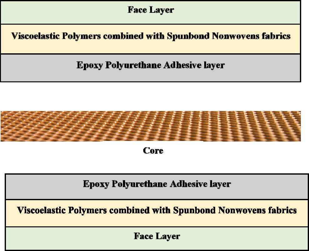
Fig. 1 despite the sandwich beam’s layers. Beam stiffness in composite constructions is impacted by local deformations, buckling, and interlaminar delamination. The composite structure consists of multiple layers with different thicknesses. The face layer is 2 mm thick, the viscoelastic polymer combined with the spunbond layer has a thickness of 0.5 mm, the epoxy polyurethane adhesive layer is 0.4 mm thick, and finally, the core has a thickness of 15 mm. Viscoelastic polymers and spunbond nonwovens, the compliant interlayers between the face layers, absorb and distribute stresses while spunbond fabric permits controlled deformation. Spunbond fabric minimizes face wrinkles and prevents the start of micro cracks between layers. Utilizing lamination has prevented the autoclave process, which makes certain shear forces stay within interlaminar bond strength parameters. Recognize the shortcomings of the current core reinforcing techniques that result in stress concentrations and integration problems. To equally distribute stresses and reduce stress concentrations, the reinforcing taper thickness increases as it penetrates the core material. Apply pre-cut adhesive films for consistent bonding, preventing buckling, and increasing beam stiffness between the reinforcement and core.
3.1. Viscoelastic autoclave spunbond interlayer bonding
The viscoelastic autoclave spunbond interlayer bonding is proposed in which compliant interlayers (viscoelastic polymers combined with spunbond nonwovens fabrics) are inserted between the face layers of a composite beam. By combining a viscoelastic polymer with a spun bond nonwoven fabric, vibrations and impact pressures are successfully reduced thanks to the polymer’s damping capabilities and the fabric’s added flexibility.
Viscoelastic polymers exhibit a distinctive property, where they undergo deformation when subjected to stress and subsequently revert to their initial form once the stress is relieved. This intrinsic characteristic renders them particularly adept at managing and redistributing stresses generated by external forces, including vibrations and impact forces. When strategically integrated within the composite beam, positioned between its face layers, viscoelastic polymers play a pivotal role in fortifying the structure’s capacity to counteract vibrations and assimilate impact energy. This infusion of viscoelastic polymers operates as a dynamic buffer, effectively dampening vibrations by absorbing and dispersing their energy. When the composite beam experiences impact forces, these polymers seamlessly engage their stress-absorbing quality, contributing to a gradual dissipation of energy over time. By augmenting the beam’s resilience through the judicious use of viscoelastic polymers, the overall performance and durability of the structure are notably enhanced. This holistic approach fosters an environment wherein the composite beam is equipped to effectively withstand the rigors of dynamic external loads, securing its longevity and dependability across diverse applications.
Spunbond nonwoven textiles are used in composite construction, adding a vital level of flexibility. The ability to manage controlled deformation within the structure itself is made possible by increased flexibility, which significantly reduces the likelihood of facial wrinkling and the development of micro cracks between layers. The composite structure is given the capacity to experience controlled deformation by the thoughtful insertion of spunbond nonwoven fabrics, avoiding the dangers connected to rapid structural changes. A harmonious balance between stiffness and flexibility is created within the composite beam by the interaction of viscoelastic polymers and spunbond nonwoven fabrics. Increased resilience in the face of various outside stressors results from this symbiotic relationship. The issue of face wrinkling, which compromises the structural integrity of the composite, is also effectively resolved by the invention of spunbond nonwoven textiles. This mitigating effect goes even further, as the regulated deformation made possible by these fabrics stops the development of micro cracks, which frequently result from structural rigidity.
Then, autoclave bonding is used in the complaint layers, which harnesses both heat and pressure to attain several critical goals within a composite structure. Its primary aims include ensuring the uniform distribution of pressure, facilitating proper consolidation of materials, and establishing robust bonding between layers. By subjecting the composite structure to the autoclave bonding process, the integration of key components like viscoelastic interlayers and spunbond nonwoven fabrics with the face layers of the composite beam is executed with precision. The utilization of autoclave bonding holds paramount significance in safeguarding against a critical issue, the potential escalation of shear stresses beyond the limits of the interlaminar bond strength. This phenomenon, known as interlaminar delamination, poses a significant threat to the structural integrity of the composite assembly. But, through the application of autoclave bonding, the risk of such stresses surpassing the bond strength is effectively mitigated. By employing elevated temperatures and regulated pressure levels, the autoclave bonding process creates an environment conducive to the meticulous integration of all constituents. This controlled environment ensures that the viscoelastic interlayers and spunbond nonwoven fabrics are seamlessly combined with the face layers of the composite beam. As a result, the bonded layers that are produced have a degree of structural cohesiveness that considerably lowers the possibility that shear stresses may reach critical values. The autoclave bonding serves as a protective measure that curtails the risk of interlaminar delamination. By arranging an environment conducive to the precision bonding of composite components, this process imparts resilience and durability to the composite structure. This helps prevent shear stresses from exceeding the interlaminar bond strength, reducing the risk of interlaminar delamination. The proposed approach addresses several critical aspects of composite beam performance, including vibration damping, impact resistance, flexibility, and interlayer bonding. By combining the properties of viscoelastic polymers and spunbond nonwoven fabrics and applying autoclave bonding techniques, create a composite structure that is better equipped to handle external loads and environmental conditions, while minimizing the potential for failure due to delamination and micro cracking between layers.
3.2. Tapered epoxy polyurethane reinforcement adhesives film
The inadequate integration between the reinforcement and the core, results in detrimental effects like buckling and localized deformations, all of which directly compromise the beam’s overall stiffness. Tapering the reinforcement thickness involves a meticulously planned strategy, characterized by a gradual reduction in the thickness of the reinforcement material. This reduction occurs as the material extends from the outer sections of the composite beam toward its core. The underlying purpose of this tapering technique is to effectively address a critical concern, the possible emergence of stress concentrations triggered by abrupt shifts in material properties. This proactive approach is crucial for preventing failures and enhancing the overall structural integrity of the composite beam. The significance of tapering lies in its capacity to establish a seamless and harmonious transition within the material composition. As the thickness gradually diminishes from the beam’s outer edges to its core, a remarkable transformation occurs in the distribution of internal stresses. This gradual alteration in thickness results in a notably smoother distribution of loads and pressures across the entire structure. This, in turn, works to counteract the potential accumulation of stresses at specific points, which could otherwise lead to localized weaknesses or even structural failures. The tapering design essentially serves as a mediating force, effectively aligning material properties and structural responses throughout the composite beam. It ensures that the beam can adeptly navigate the challenges posed by external loads without succumbing to stress concentrations that might compromise its integrity. In essence, the tapering of reinforcement thickness stands as a testament to meticulous engineering, offering a holistic approach to not only optimizing the beam’s load-bearing capacity but also fortifying it against potential vulnerabilities within its structure. This thoughtful integration of design principles underscores the delicate balance between robustness and functionality, resulting in a composite beam that is resilient, reliable, and primed for demanding applications.
Then, epoxy polyurethane adhesive films represent pre-cut adhesive sheets meticulously positioned between the tapered reinforcement and the core material of the composite beam. Functioning as a fundamental bonding agent, these adhesive films seamlessly fuse the reinforcement with the core, securing structural integrity. The uniformity of the bond line thickness emerges as a critical factor for dependable bonding. Here, the pre-cut nature of the adhesive films plays a pivotal role, ensuring consistency in bond line thickness across the interface. This uniformity acts as a safeguard against potential inconsistencies that might otherwise generate weak points or uneven stress dispersion. The adhesive films are meticulously designed to counteract a specific challenge during the bonding process, excessive adhesive squeeze-out. This phenomenon, if uncontrolled, leads to unwanted material displacement, manifesting as undesirable outcomes like buckling or local deformations. The adhesive films expertly circumvent these issues, maintaining a controlled and stable bonding process. By precisely regulating adhesive displacement, they curtail the likelihood of distortions, thereby guaranteeing a cohesive and uniform bond between the reinforcement and the core material. The utilization of epoxy polyurethane adhesive films stands as a testament to precision engineering. These films not only ensure reliable bonding between the composite beam’s components but also contribute to the structural stability of the entire assembly. Their role in preventing excessive adhesive squeeze-out strengthens the beam’s durability and performance by mitigating deformations that could compromise its overall stiffness. As a result, the adhesive films foster a synergy of strength and stability within the composite structure, culminating in a beam that is optimized for resilience and adept at withstanding external forces.
Overall, the viscoelastic polymers and spunbond nonwoven textiles are used to create compliant interlayers, which are positioned thoughtfully between the face layers of a composite beam. Viscoelastic polymers can absorb and equally distribute the stresses of external loads because of their capacity to deform under tension and then return to their original shape when the stress is released. Spunbond nonwoven fabric is used to increase flexibility, allowing for controlled deformation inside the composite structure and preventing the production of micro cracks between layers. To consolidate this advanced composite structure, autoclave bonding is employed, ensuring uniform pressure distribution during curing and fostering robust bonding between the layers, and avoiding the risk of interlaminar delamination within the sandwich beam by ensuring that shear stress does not exceed the interlaminar bond strength. Tapered core reinforcement gradually reduces the thickness of the reinforcement as it penetrates the core material. Epoxy polyurethane adhesive films, which are used between the reinforcement and core material minimize excessive adhesive squeeze-out during the bonding process and ensure uniform bond line thickness, these pre-cut adhesive films improve the rigidity of the beam while avoiding buckling and localized deformations.
3.3. Scientific hypothesis
Composite sandwich structures are becoming increasingly popular as replacements to traditional materials in engineering applications due to their advantageous properties. However, obstacles like as interlaminar delamination and local deformations impede their performance. To overcome this, a novel technique, viscoelastic autoclave bonding with tapered epoxy reinforcement polyurethane films, is developed. To reduce delamination and increase structural integrity, this approach uses combined viscoelastic nonwovens compliant interlayers and autoclave bonding. Tapered epoxy polyurethane reinforcement adhesive films are also used to distribute stresses evenly and minimize local deformations, which improves beam stiffness and performance.
4. Result and Discussion
The results obtained from the proposed model have been provided in this section. The results showed that the proposed model minimized the formation of micro cracks, and improved interlaminar bond strength, and the stiffness of the beam of the proposed approach is also proved by comparing it with other existing approaches.
4.1. Experimental setup
The experimental setup aimed to assess the effectiveness of the proposed model in minimizing microcrack formation, enhancing interlaminar bond strength, and improving beam stiffness compared to existing approaches. The testing environment utilized for these evaluations is detailed below.
• OS: Windows 10 Professional 64-bit
• RAM: 8 GB
• Processer: intel(R) Core (TM) i3-4130 CPU @ 3.40 GHz 3.40 GHz
• Tool: Matlab
The MATLAB software was chosen for its versatility in numerical simulations and analysis, allowing for a comprehensive evaluation of the proposed model’s effectiveness. The hardware specifications ensure sufficient computational power for running simulations and processing data. During the experiments, the MATLAB tool facilitated the implementation of the proposed model, enabling the simulation of various loading conditions and analyzing the behavior of the composite sandwich structure. The experimental setup was meticulously designed to ensure accurate and reproducible results, crucial for validating the efficacy of the proposed approach in minimizing micro cracks, enhancing interlaminar bond strength, and improving beam stiffness.
4.2. Performance metrics of the proposed model
The performance metrics of the proposed model in the composite sandwich beam and the stiffness of the proposed approach based on the achieved outcome are explained in detail in this section.
Fig. 2 illustrates the performances of the deflection of the proposed model. When the load is 0 KN it achieves the minimum deflection of 0 mm and the load increases, the deflection range also increases, and while the load is 160 KN, it achieves the maximum deflection of 35 mm, compared to the existing method which is low. The viscoelastic polymers absorb and disperse stresses carried on by external loads and then come to their original shape thereby reducing of deflection of the beam.

Fig. 3 illustrates the performances of the stress and strain of the proposed model. When the stress is 3 MPa, it achieves a maximum strain of 2 and while the stress is 0.5 MPa, it achieves a minimum strain of 0.25. Beam strain is lowered as a result of the viscoelastic polymer and spunbond nonwoven fabric’s efficient reduction of vibrations and impact pressures along with their increased flexibility.

Fig. 4 illustrates the performances of the deflection at the temperature of the proposed model. When the temperature is 40 °C, it achieves a maximum deflection of 8 mm and when the temperature is 5 °C, it achieves a minimum deflection of 2 mm. Autoclave bonding is the ability to handle high temperatures by creating an environment conducive to the meticulous integration of all constituents so that deflection is reduced.
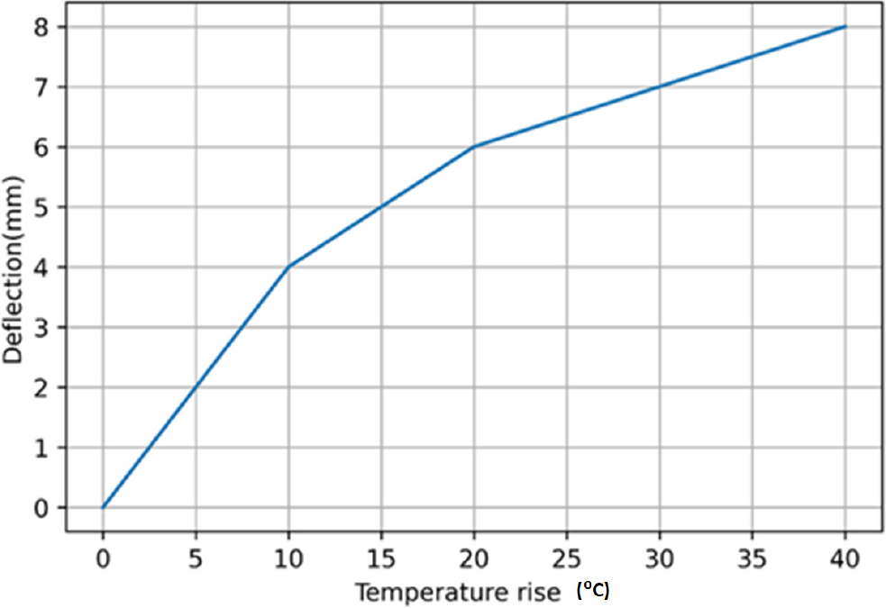
Fig. 5 illustrates the performances of the adhesive film strength of the proposed model. When the interfacial bonding strength increases, the adhesive film strength also increases from 0 to 9.5. Epoxy polyurethane adhesive films have a consistent bond line thickness, which leads to increased interfacial bonding strength.

Fig. 6 illustrates the performances of the deformation of the proposed model. When the load is 200 Pa it achieves the minimum deformation of 44.3 mm and while the load is 1,000 Pa, it achieves the maximum deformation of 56 mm. Epoxy polyurethane adhesive sheets improve the stiffness of the beam by preventing excessive adhesive squeeze-out during the bonding process, which helps to reduce deformations.

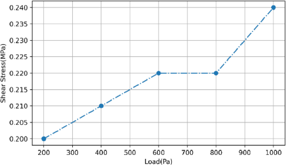
Fig. 7 illustrates the performances of the shear stress of the proposed model. When the load is 200 Pa it achieves the minimum shear stress of 0.200 MPa and while the load is 1,000 Pa, it achieves the maximum shear stress of 0.240 MPa. Autoclave bonding helps to achieve uniform pressure distribution and strong bonding between layers, thereby avoiding the exceeding of shear stress.
The comparison of the performance of the proposed approach with other existing approaches is discussed in the next section 4.4.
4.3. Comparison of proposed model with previous models
This section highlights the proposed method’s performance by comparing it to the outcomes of existing approaches and showing their results based on various metrics.
Fig. 8 depicts the comparison of the displacement of the proposed model with other existing approaches. The proposed approach is compared with existing techniques such as MZZT and GLHT.28) The proposed model obtains the value of 6 mm whereas the MZZT and GLHT are 6.10 mm and 6.30 mm. The displacement of the proposed model is low whereas the displacement of GLHT is high.

Fig. 9 depicts the comparison of the stress and strain of the proposed model with other existing approaches. The proposed approach is compared with existing techniques such as CB-0.1 % CNT and CB-pure.29) The proposed model obtains a strain value of 1 whereas CB-0.1 % CNT and CB-pure are 1.22 and 1.2. The strain of the proposed model is low whereas the strain of CB-0.1 % CNT is high.

Fig. 10 depicts the comparison of the strength of the proposed model with other existing approaches. The proposed approach is compared with existing techniques such as RPC, HS-SHCC, and DHS-SHCC.30) The proposed model obtains a value of 7 whereas the RPC, HS-SHCC, and DHS-SHCC are 3.2, 4.7, and 5. The strength of the proposed model is high whereas the strength of RPC is low.
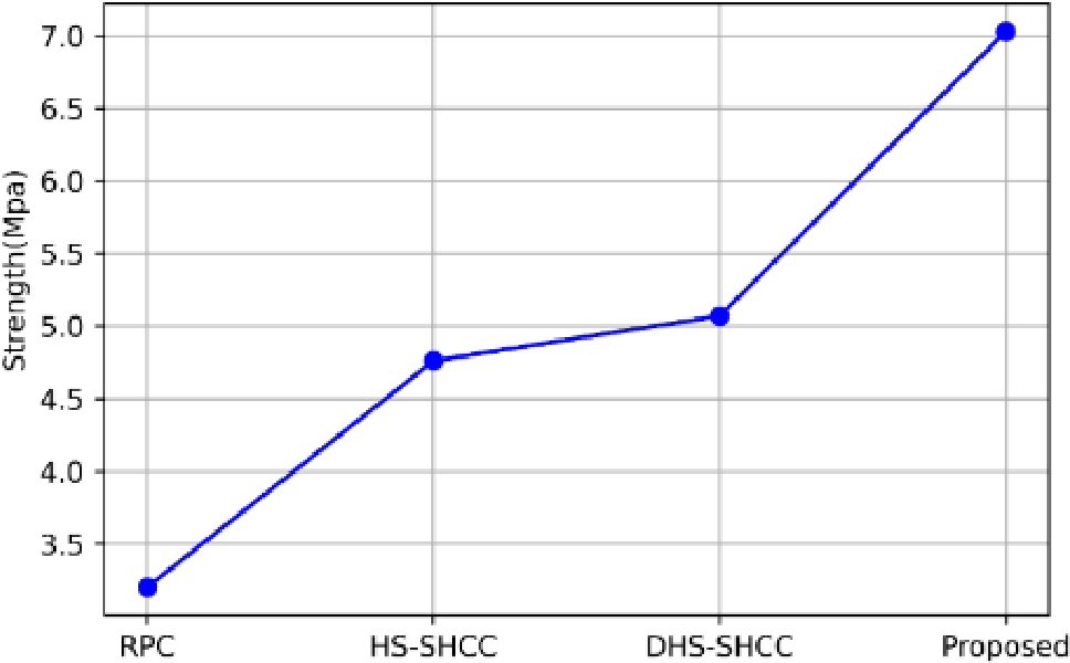
Fig. 11 depicts the comparison of the load efficiency of the proposed model with other existing approaches. The proposed approach is compared with existing techniques such as EBEGO, BS 8006, and AND CUR 226.31) Load efficiency of existing methods such as EBEGO, BS 8006, and CUR 226 has a value of 80 %, 54 %, and 81 %. The proposed system has a better load efficiency of 83 %. The load efficiency of the proposed model is high whereas the load efficiency of BS 8006 is low.
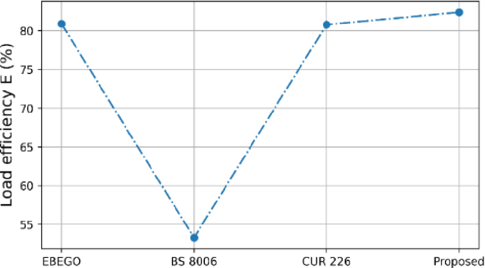
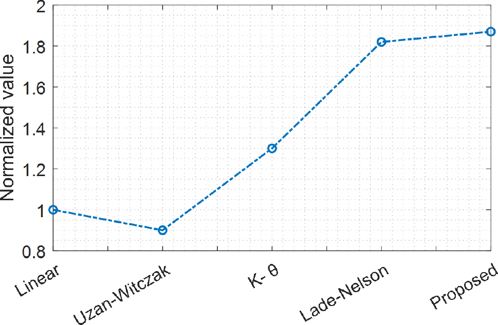
Fig. 12 depicts the comparison of the normalized value of the proposed model with other existing approaches. The proposed approach is compared with existing techniques such as the linear model, Uzan-Witczak, k-θ, and Lade-Nelson.32) Load efficiency of existing methods such as the linear model, Uzan-Witczak, k-θ, and Lade-Nelson has a value of 1, 0.9, 1.3, and 1.8. The proposed system has a better load efficiency of 1.89 points. The normalized value of the proposed model is high whereas the Uzan-Witczak is low.
Overall, the proposed method has a good result compared to the existing method, when the load is applied on the beam, the displacement of the beam is 6 mm, compared to the existing method, the proposed is low. The proposed method improves the stiffness of the beam, the strain value is 1, and during the temperature rise the deflection is 8 mm, when compared to the existing method, the proposed method obtains good results. As a result, the proposed method gives low deflection, low deflection under temperature rise, and high stiffness.
5. Conclusion
In conclusion, a unique viscoelastic autoclave bonding with tapered epoxy reinforcement polyurethane films is suggested, which successfully addresses problems such as interlaminar delamination, local deformations, and failures in core indentation, hence improving the performance over previous approaches. Improved structural integrity and decreased deflection result from the combination of spunbond nonwoven textiles and viscoelastic polymers, which lessen vibrations and impact forces. In addition, the application of epoxy polyurethane adhesive films with tapered reinforcement and homogeneous bond line thickness guarantees strong interfacial bonding and uniform stress distribution, which improves beam overall performance. In terms of deflection under load, the proposed model achieves a maximum deflection of 35 mm at 160 KN load, outperforming existing methods. The stress-strain relationship showcases superior strain reduction, with a maximum strain of 2 at 3 MPa stress. Additionally, the stiffness of the proposed model is notably enhanced, with a stiffness value of 7, surpassing RPC, HS-SHCC, and DHS-SHCC. Furthermore, the proposed model exhibits an excellent load efficiency of 83 %, outshining EBEGO, BS 8006, and CUR 226. Additionally, the normalized value stands at 1.89 points, indicating a substantial improvement over existing techniques such as Uzan-Witczak. These quantitative measures underscore the significant advancement this methodology represents in composite sandwich beam design. Overall, the proposed method performs well when compared to the existing methods and not only addresses critical structural concerns but also sets new standards for performance and efficiency in composite construction.
