

1. Introduction
Al electrolytic capacitors are widely used in electronic devices because of advantages such as large specific capacitance and low cost.1) The recent development of small-volume electronics requires an increase in the capacitance of Al electrolytic capacitors.2) The capacitance (C) of an Al electrolytic capacitor is expressed as
where ε0 is the vacuum permittivity, ε is the relative dielectric constant of the anodic oxide film, A is the effective surface area, and d is the film thickness.
Barrier anodic Al2O3 films formed by anodizing an Al foil can have either an amorphous or crystalline structure depending on the growth conditions.3) Generally, the crystalline oxide can sustain a higher voltage, has a higher relative dielectric constant, and has a lower ionic conductivity than those of the amorphous oxide film.4) Thermal Al oxide, formed during post-heat-treatment of Al foils, acts as nuclei for the amorphous Al2O3 to γ ′- Al2O3 transformation and can retard the growth of the oxide during the anodization, consequently decreasing the film thickness.5) Reanodization of the Al oxide can extend the crystallinity in the film and help seal the defects, resulting in an improved electrical stability of the anodized oxide film. Besides, the anodizing electrolyte also has a great effect on the microstructure and crystallinity of the anodic oxide film. Ban et al.6) found that anodization of the etched Al foil in a mixed solution of boric acid and citric acid could improve the crystallinity of the oxide film, whereas the electrical stability of the film decreased because of defects formed by phase transformation.
To enhance the capacitance of an anode foil, many studies have been performed on Al foils by incorporating high-dielectric-constant (high-K) materials and anodic oxide film. Dielectric materials such as ZrO2, Nb2O5, SiO2, (Ba0.5Sr0.5) TiO3, Bi4Ti3O12, and TiO2 were used to coat the Al foil.7-11) It has been found that the specific capacitance can be improved by a composite oxide layer with a high dielectric constant. To use composite oxide dielectrics in high-voltage capacitors with high capacitance, it is necessary to form composite oxide films within long Al etch pits that are 20-50 μm long. However, few studies have been conducted on etched Al foil. A uniform coating on etched Al foil for high voltage is very difficult because of the deep and narrow pit structure. Our previous research showed that the vacuum infiltration method was an effective way to coat ZrO2 films on etched Al foil.12) Meanwhile, the effect of coating layers of high-K materials on the electrical properties of etched foil is still not clear. In this work, ZrO2 layers were coated on etched foil, and anodized at 100 V and 600 V in boric acid. The effect of coating thickness on the electrical properties of Al foils with composite oxide layers is discussed.
2. Experimental procedure
2.1 Sample preparation
High-purity (99.99 %) etched Al foil was used as the substrate. The thickness, pit diameter, pit length, and pit density of the Al foils were approximately 100 μm, 1-2 μm, 30-40 μm, and 2.0 × 107 cm–2, respectively. A sol-gel method was employed to prepare ZrO2 films. The reagents used for preparing the solution were zirconium (IV) butoxide, 2-methoxyethanol, nitric acid, and acetic acid. The molar ratio of acetic acid to zirconium was 6, and nitric acid was added as an acid catalyst to prevent hydroxide precipitation.
ZrO2 film was coated on etched Al foil using the vacuum infiltration method and annealing. First, ZrO2 sol was injected into the high vacuum chamber until the samples were immersed followed by withdrawal in air at a constant speed. Second, the coated samples were dried at 100 °C and annealed at 500 °C. The processes were repeated n (n = 1, 2, 4, 8) times. Finally, the coated samples were anodized at 100 V and 600 V with 50 mA/cm2 constant current in a boric acid (H3BO3) solution (100 g H3BO3/1 L H2O) at 85 °C and heat-treated at 500 °C for 2 min. The samples without ZrO2 were also anodized under the same conditions for comparison. Further details of the preparation of the sol solution and coating process are described elsewhere.12)
2.2 Characterization
The cross-sectional morphologies of the samples were examined using field-emission scanning electron microscopy (FESEM, JSM-6700F, JEOL, Japan). The samples to be examined by transmission electron microscopy (TEM) were thinned using a focused ion beam (FIB, versa 3D LoVac, FEI, USA). The structure and composition of the thin tunnels were characterized using field-emission transmission electron microscopy and energy dispersive X-ray spectroscopy (FETEM-EDS, Titan G2 ChemiSTEM CsProbe, FEI, USA). The capacitance and dissipation factor for each specimen was measured using an impedance-gain phase analyzer (Hewlett-Packard, 4194A) in water (1000 mL) and an ammonium pentaborate (NH4B5O8·4H2O, 80 g) mixture. Electrical properties, such as the ability to withstand voltage and leakage current, were characterized using a source meter (Keithley, 2410) in a water (1000 mL) and boric acid (H3BO3, 70 g) mixture.
3. Result and Discussion
The cross-sectional structures of coated tunnels examined by SEM are shown in Fig. 1. To obtain SEM images of the tunnels, the samples were polished and corroded in potassium hydroxide (KOH) solution for 2 min. Figs. 1(a)-(d) show pits for the samples coated 1 to 8 times. It is clear that the ZrO2 films were successfully coated on deep etched tunnels of the Al foil, and the thickness of the coating layer increased with the number of coating layers. The thicknesses of the ZrO2 coating layer changed from 25 nm to 220 nm as the number of coating layers were increased from 1 to 8. ZrO2 coating layers show dense morphologies with an increasing number of coating layers. An empty space is observed between the ZrO2 coating layer and the Al etch pit, which is caused by shrinkage during annealing at 500 °C and corrosion by the KOH solution.
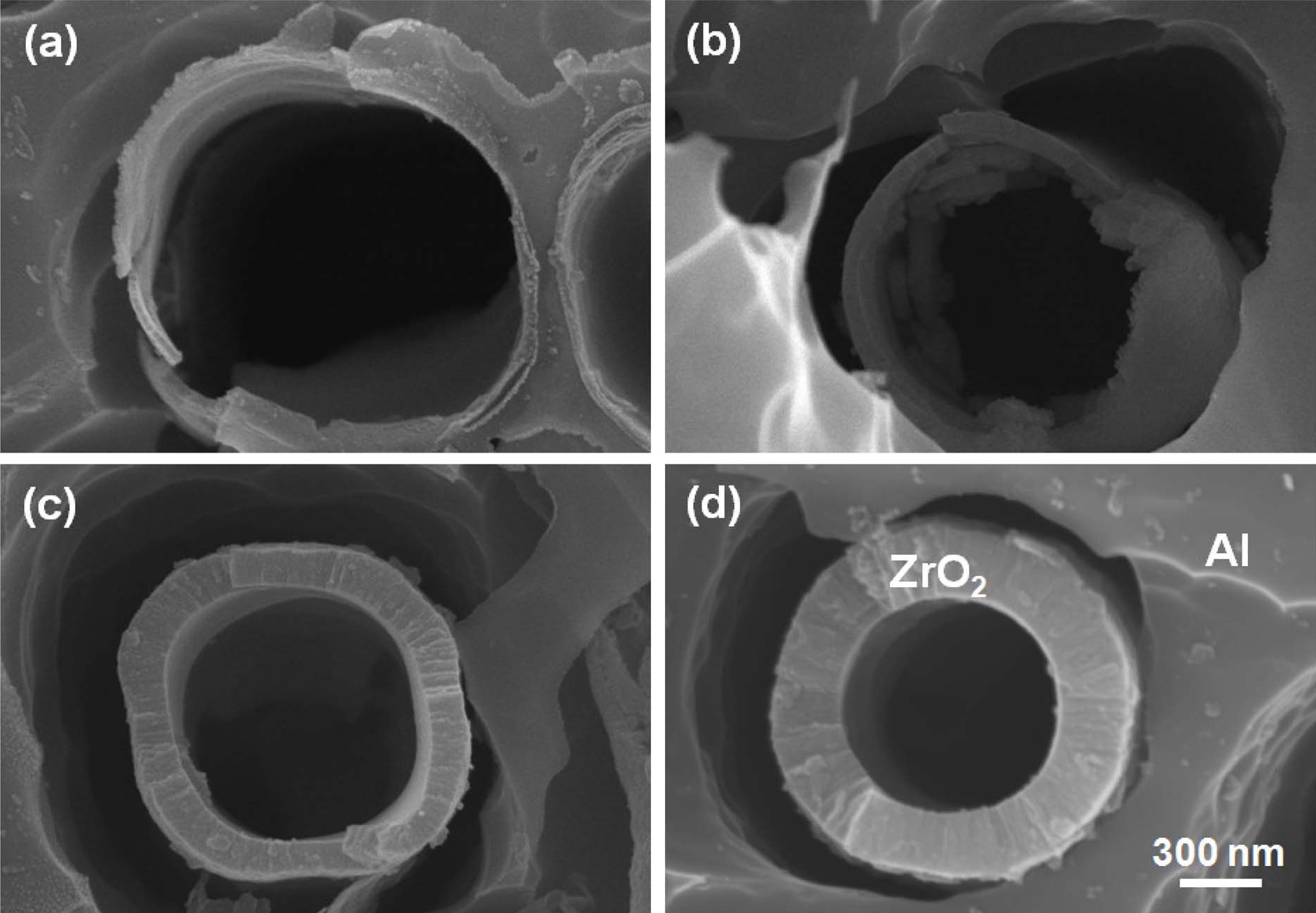
Fig. 1.
Cross-sectional SEM images of tunnels with different coating times: (a) 1, (b) 2, (c) 4, and (d) 8 times.
After being anodized at 100 V, the samples were analyzed by TEM. Figs. 2(a) and (b) are the TEM images of samples coated 1 and 4 times, respectively. According to our previous research, the prepared oxide layer is a multi-layer structure, which has an inner Al hydrate layer, Al-Zr composite layer in the middle, and outer Al2O3 layer.12) It was confirmed that the ZrO2 layer was successfully coated on the etch pits, and the thickness of the ZrO2 coating layer (black color) was approximately 24 nm and 100 nm, respectively. In the sample coated once, the outer Al2O3 layer consisted of two distinct zones. The Al2O3 layer with a smooth surface found at the Al substrate/Al2O3 interface showed an amorphous structure and the rest was a crystalline oxide layer. Similar results were observed when the Al foil was anodized in an ammonium adipate solution.13) The Al2O3 layer in a sample coated 4 times showed a crystalline structure. The structural change of the Al2O3 layer with an increasing number of coatings is because of the thermal Al oxide layer formed by annealing. The repeated heat-treatment of Al foil at 500 °C before or after anodizing could induce the formation of crystalline γ ′-Al2O3 in the anodized oxide film.5) Besides, more uniformly distributed voids and higher concentration near the metal side are evident in a sample coated 4 times. Figs. 2(c) and (d) are the EDS line profile results for the sample coated once and 4 times, respectively. The changes in the Al intensity from the inner layer to the outer layer indicated that Al3+ ions were transported inwards through the coating layer during anodization. The thicknesses of the Al-Zr composite oxide layer increased from 15 nm to 35 nm as coating times increased from 1 to 4.
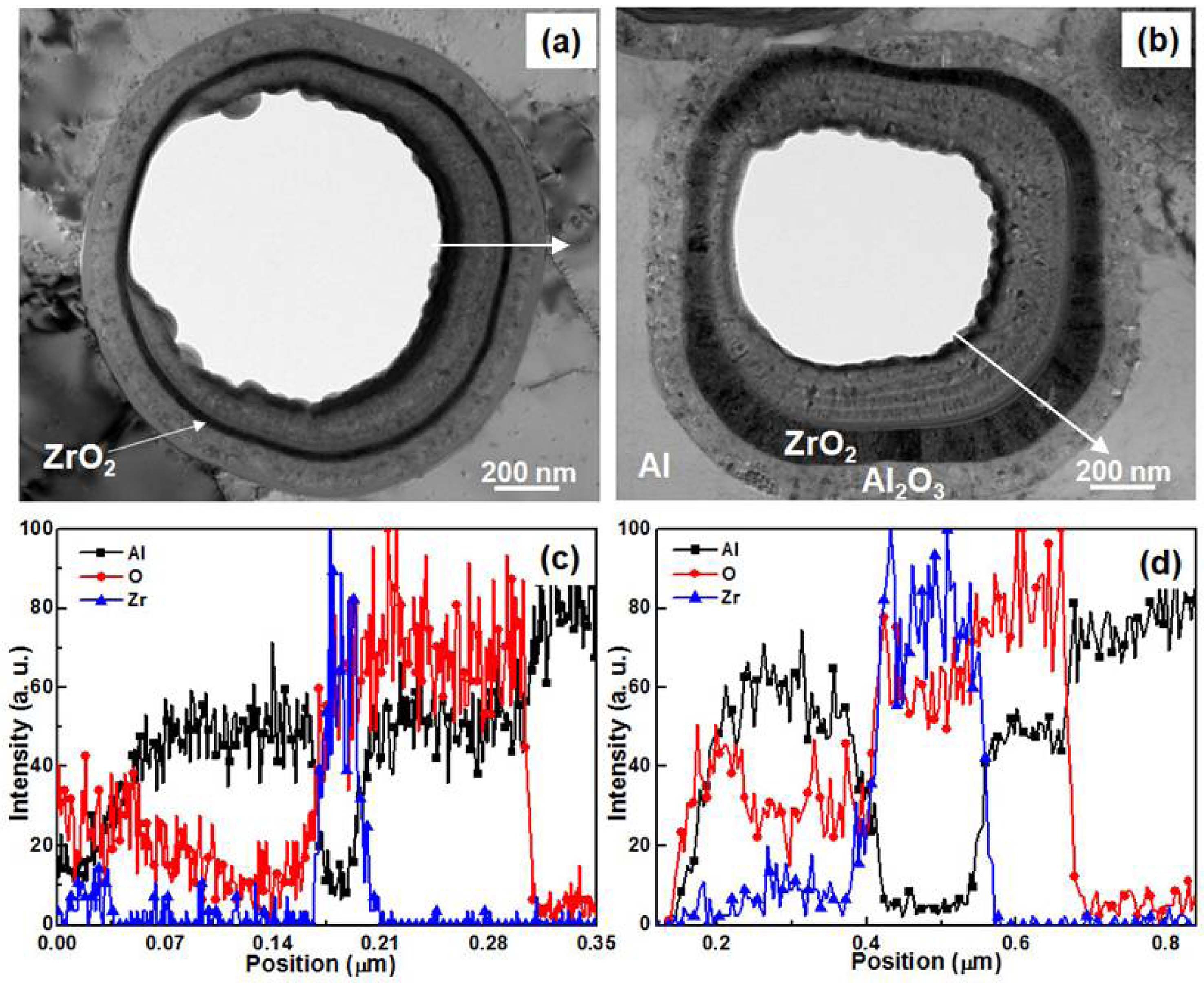
Fig. 2.
TEM images and EDS line profiles of tunnels anodized at 100 V for samples coated: (a) and (c) once, and (b) and (d) 4 times.
Fig. 3(a) shows the HR-TEM image of the interface of the ZrO2 coating layer and the outer Al2O3 layer. Both layers exhibited a crystalline structure. The lattice image of the ZrO2 layer is shown in Fig. 3(b). The measured interplanar spacing, d, is 0.294 nm corresponding to the (011) plane of tetragonal ZrO2. Figs. 3(c) and (d) show the selected area electron diffraction patterns of the ZrO2 coating layer and the outer Al2O3 layer. The calculated d of the diffraction rings from Figs. 3(c) and (d) match well with the JCPDF cards (card No. 50-1089 and card No. 02-1420), respectively. It was demonstrated that the ZrO2 coating layer was tetragonal and the anodic outer layer was a γ-Al2O3 structure.
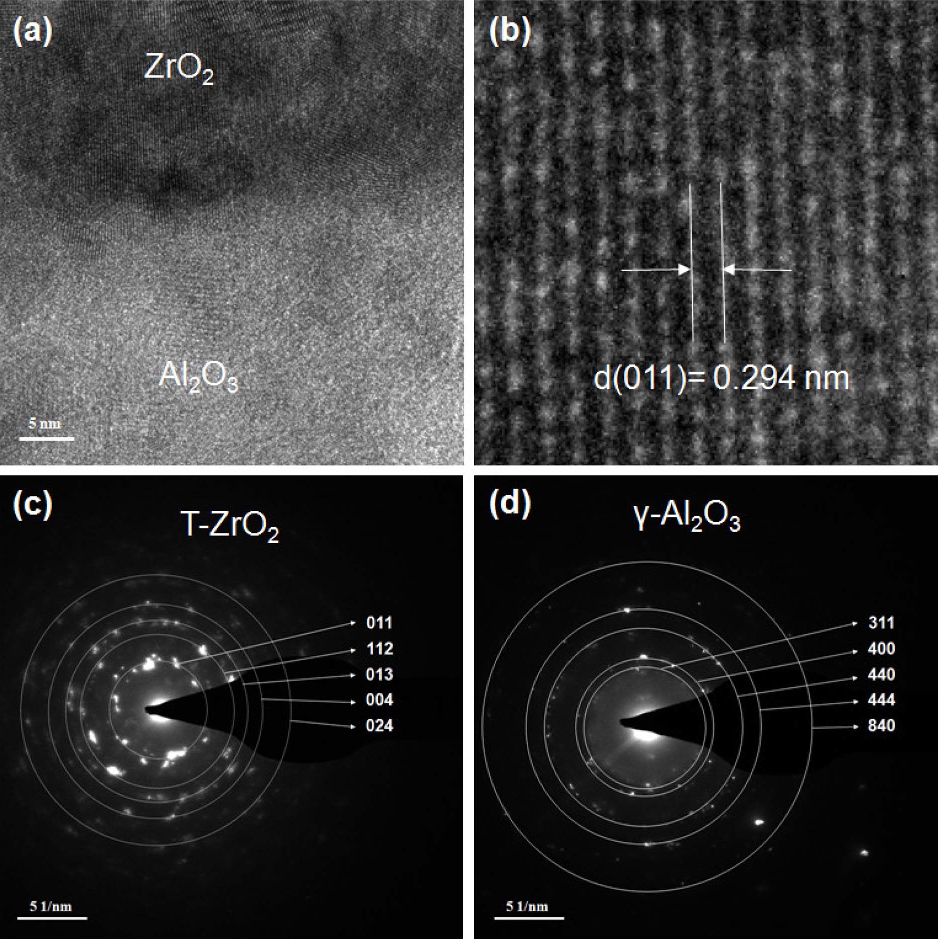
Fig. 3.
HRTEM analysis of an anodized sample coated 4 times: (a) HRTEM image of the interface of the ZrO2 coating layer and the outer Al2O3 layer, (b) magnified HRTEM image of the ZrO2 coating layer. (c) and (d) Selected area electron diffraction patterns of coating layer and Al2O3 layer.
The electrical properties of the samples, such as leakage current and withstanding voltage were tested after being anodized at 100 V. As shown in Fig. 4(a), samples with different coating thickness showed similar leakage current at 100 V, but the leakage current increased over the range 0-50 V as the number of coating layers increased from 1 to 8. This is because of the presence of voids with electrical instability; it allows the water to accumulate in the crystalline film interior during testing. Alwitt et al.14) reported that the discrete voids with a diameter of 2-4 nm and densities in the range of 1011-1012 cm–2 are responsible for the electrical instability of the anodic Al2O3 film. The leakage current of samples decreased due to the healing of voids by applied voltage after around 50 V. The withstanding voltages of all samples are approximately 120 V. Fig. 4(b) shows the change in capacitance and the thickness of the middle layer for these samples as a function of number of coating layers. The capacitances of samples increased from 1.96 to 2.68 μF/cm2 when the number of coating layers, n, increased from 0 to 8. The capacitance of a sample with a ZrO2 coating layer was 36.3 % higher than that of a sample without a coating layer. The increase in capacitance was mainly due to the increase in the middle Al-Zr composite layer. The percentage thickness of the middle layer increased with the number of coating layers, as shown in Fig. 4(b). Therefore, the formation of an Al-Zr composite oxide with a high dielectric constant by incorporation of a ZrO2 layer and Al oxide during anodization resulted in an increase in the capacitance.
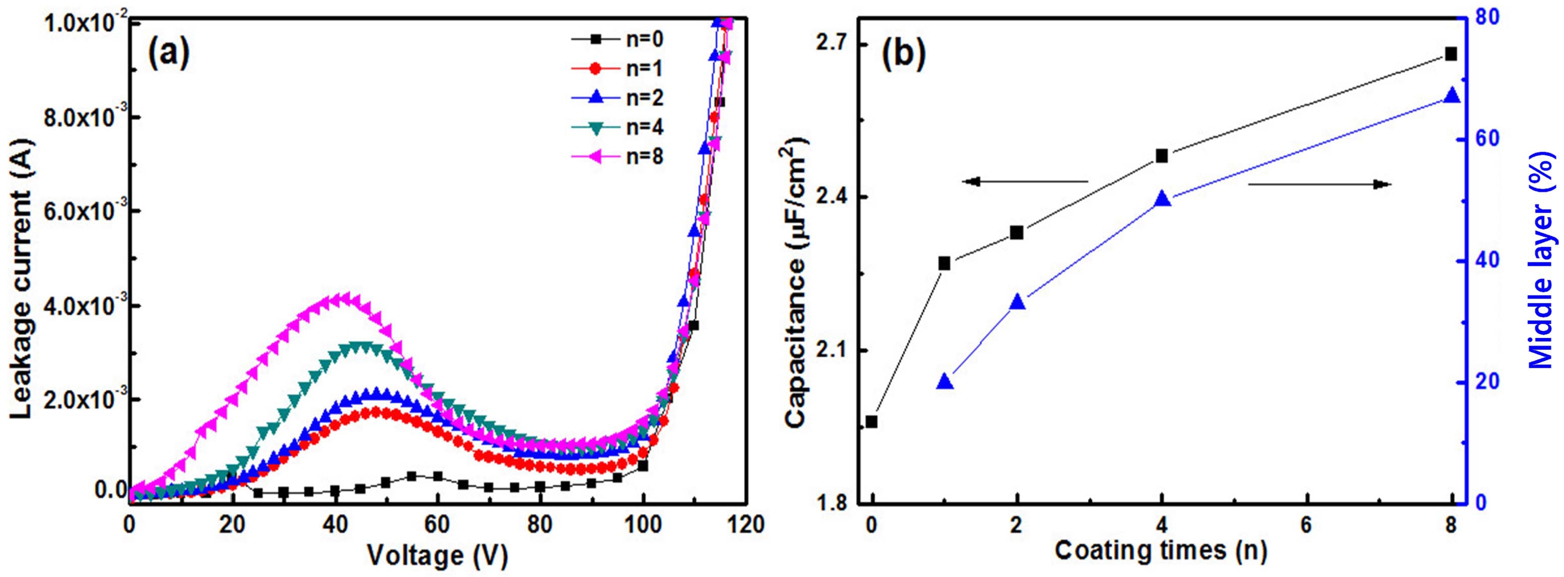
Fig. 4.
(a) Leakage current and (b) capacitance variation of tunnels anodized at 100 V after different coating layers.
Fig. 5 shows the cross-sectional SEM images of samples anodized at 600 V for different numbers of coating layers. Fig. 5(a) is a tunnel without a coating layer (n = 0), (b), (c), (d), and (e) are tunnels with 1, 2, 4, and 8 coating layers, respectively. It was observed that the tunnels with a coating layer have a dual layer structure, which is composed of an inner layer and an outer layer. The total thickness of the oxide layer increased from 600 nm to 740 nm when n increased from 0 to 8. It is apparent that the inner diameters of the samples coated once and twice after anodization are smaller than those of the ZrO2-coated samples shown in Fig. 1. This indicated that shrinkage occurred in the ZrO2 coating layer during anodization. Our previous research on a sample coated 4 times showed that the ZrO2 coating layer can be preserved during anodizing.12) It demonstrated that the ZrO2 coating layer could sustain the volume expansion of anodic Al2O3 under an anodizing voltage of 600 V when the number of coating layers is more than 4.
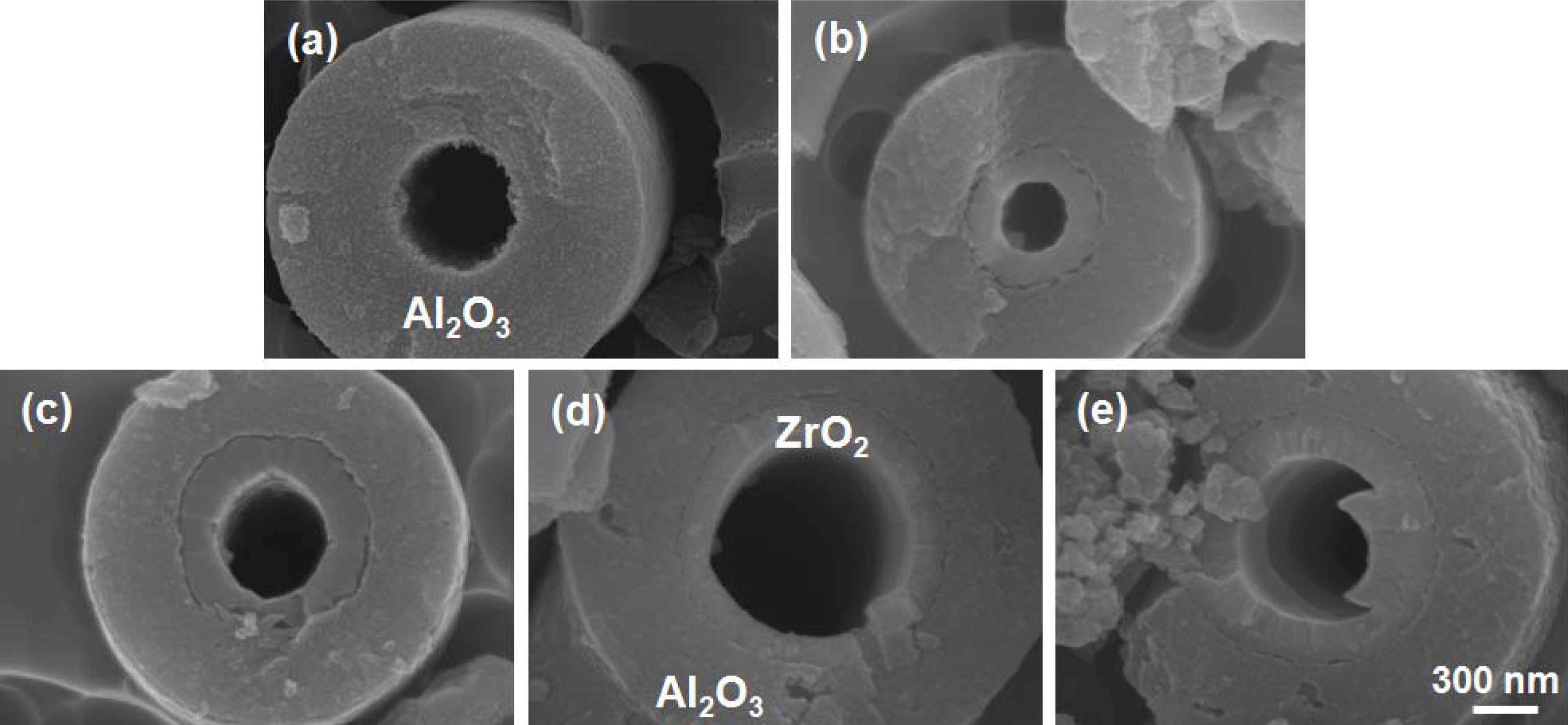
Fig. 5.
Cross-sectional SEM images of samples coated with different number of layers anodized at 600 V: (a) non-coated, (b) 1, (c) 2, (d) 4, and (e) 8.
Fig. 6(a) shows the leakage current properties of anodized samples with and without any coating. It indicated that the leakage currents of all samples are similar. The withstanding voltages of all samples not shown here are approximately 640 V. Fig. 6(b) shows the influence of coating times on the capacitance. The capacitances of the samples at 1 kHZ are 0.40, 0.35, 0.39, 0.51, and 0.48 μF/cm2 for n = 0, 1, 2, 4, and 8, respectively. In order to understand the changes in the capacitance with coating thickness, the capacitance is approximately calculated using the following equation
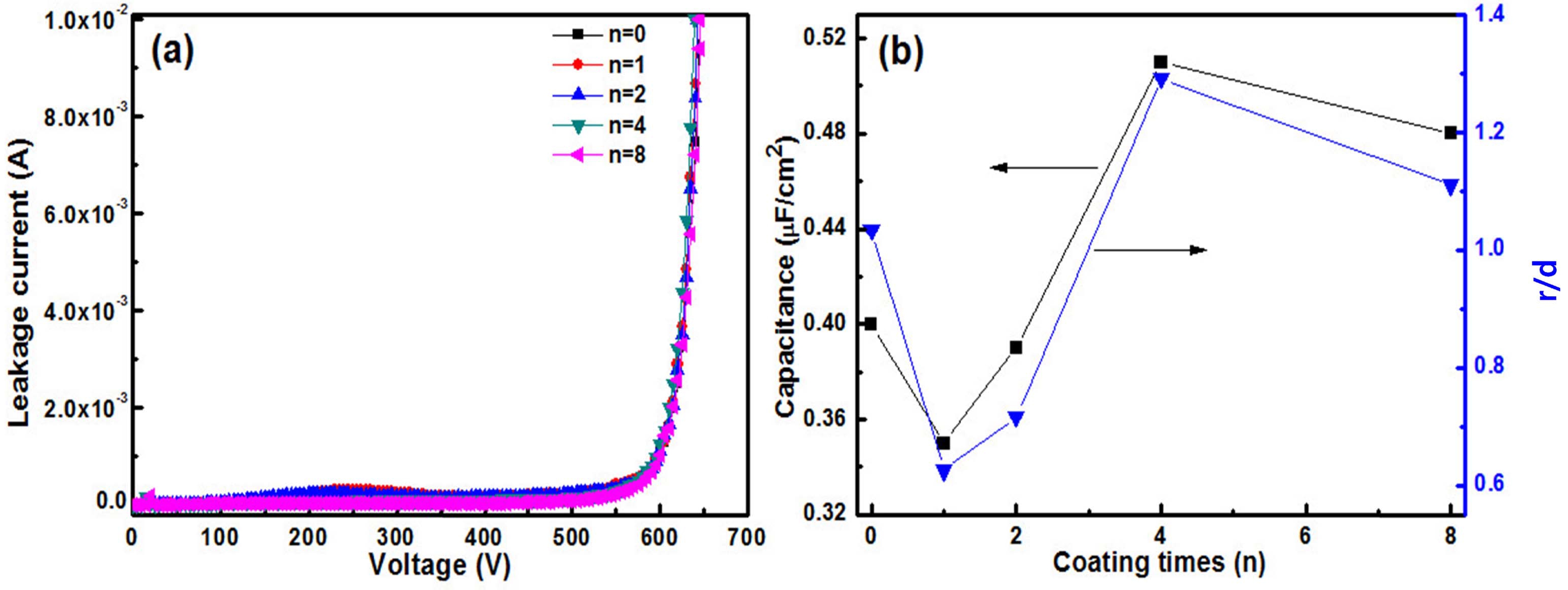
Fig. 6.
(a) Leakage current and (b) capacitance variation of tunnels anodized at 600 V after different number of coating layers.
where r is the inner diameter of the tunnel, h is the length of the tunnel, and d is the total thickness of the oxide layer. This equation is suitable for calculating the capacitance of a single tunnel. If εr and h of all the tunnels are the same, the capacitance is proportional to the ratio r/d. The statistical results of r/d shown in Fig. 6 (b) show a similar trend with capacitance. The highest r/ d is obtained from a sample coated 4 times. This indicated that the increasing surface area is the main reason for the increase in the capacitance for a coating layer that can withstand the volume expansion during anodizing. The decrease in capacitance for samples coated once and twice is because of the low r/d of the tunnels. The capacitance of a sample coated 4 times shows an increase of 27.5 % compared to the samples without ZrO2 coating.
The reasons for the increase in capacitance are different depending on the anodizing voltage. When anodized at 100 V, the ratio of the composite oxide layer to the total oxide layer may play a critical role in increasing capacitance. However, when anodized at 600 V, the ratio of the composite oxide layer to the total oxide layer is comparatively low. Therefore, we assumed that the inner diameter of the tunnel might play an important role because of the effect on effective area
4. Conclusion
ZrO2 thin films were successfully coated on etched Al foil using the vacuum infiltration method. The thickness of the ZrO2 coating layers increased by approximately 25 nm per coating layer. A multi-layer structure (inner Al hydrate layer, middle Al-Zr composite layer, and outer Al2O3 layer) was obtained for the ZrO2-coated Al foil after anodization. For the samples anodized at 100 V, the crystallinity of the outer Al2O3 layer was improved with an increasing number of coating layers because of the formation of a thermal Al oxide layer during anodization. The increase in capacitance was mainly due to the increase in the middle Al-Zr composite layer. For samples anodized at 600 V, the thickness of the coating layers plays an important role in increasing the effective area because the coating layer can withstand the volume expansion during anodization. The capacitances of samples with the ZrO2 coating were 36.3 % and 27.5 % higher than those of the samples without the coating when anodized at 100 V and 600 V, respectively. This suggests that the vacuum infiltration method is an effective way of increasing the specific capacitance of high-voltage Al foils.
