

1. Introduction
Direct methanol fuel cell (DMFC) is seen as the most viable of the type of fuel due to its advantages such as easy handling, light weight, easy to be moved, and environmentally friendly. Therefore DMFC was developed as a source of green energy fuel cell with a simple device.1-3) One important component of the DMFC is a polymer electrolyte membrane (PEM), which serves as the electrolyte separator between the cathode and anode. PEM has been developed extensively is perflurosulfonat acid membrane (Nafion ©).4) Commercial membrane types nafion in general has been successfully used because it has good chemical stability and high proton conductivity. This membrane nevertheless has several disadvantages, including high cost, high methanol crossover, work at relatively low temperatures (<100 °C) and rapid dehydration with decreasing proton conductivity at high temperatures.5,6)
Synthesis proton exchange membrane (PEM) of organic materials as matrix and inorganic materials as fillers known can be better properties of membrane. Examples of the organic matrix which is easily available and is the waste that still less widely used is chitosan. Chitosan is a natural polysaccharide result of deacetylation mechanism of chitin, which can be obtained from shrimp shell.7,8) Chitosan is a biopolymer that is easy to set up, biodegradale, and non-toxic. Chitosan also has hydrophilic properties, form a good movie, and easily obtained from fishing waste.9-12)
Chitosan as organic biopolymers can be combined with an inorganic material to produce a composite membrane. Several investigators have reported the manufacture of composite membranes based on chitosan, including Mat et al.13) synthesize the composite membrane remedy DMFC applications. Synthesized membrane with a matrix of chitosan and CaO as an inorganic filler showed low methanol permeability, because CaO which has hydrophobic properties make the membrane can withstand the movement of protons, thereby reducing methanol crossover. Another composite membrane has been reported by Shahi et al.14) making a composite membrane with a blend of chitosan as an organic material and inorganic material which is silica. Combination of the two materials organicinorganic interactions occured in membrane composites that can suppress of methanol crossover and maintain the presence of water in the membrane to becomes a medium for the movement of protons to obtain a high proton conductivity.
Another of inorganic material has potential as filler is montmorillonite (MMT). MMT is a kind of aluminosilicate clay from the group consisting of a layer of silica tetrahedral and octahedral structure alumina. Parallel layers in the structure along with the interrelated forming electrostatic force.15,16) With a crystal structure that has a blank space and the presence of hydroxyl groups on its surface allows for adsorption occurs and interacts with organic compounds. MMT has a large specific surface area, demonstrated the ability to absorb, cation exchange capacity, and improved adhesive.17)
In the present study, composite membranes of chitosan incorporated with PTA supported onto MMT have been fabricated and characterized. The advantage of this system is that the composite membranes shown good mechanical properties and compounds acid-free bonding structure from PTA group as medium of protons trajectories. Thus, the chitosan composite membranes with PTA crosslinked not only exhibited low water uptake and low methanol crossover, but also achieved high proton conductivity. Although many modifications have been made on CS with PTA or CS with clay as mentioned above, chitosan composite membrane incorporated with PTA entrapped onto MMT has not been studied.
2. Research Method
2.1 Materials
The dried shrimp shell powder of penaeusmonodon. Montmorillonite (MMT) powder, and phosphotungstic acid (PTA) was purchased from Sigma Aldrich. Sodium hydroxide (NaOH), hydrochloric acid (HCl), methanol (MeOH), acetic acid, phenolphtalein indicator, and sodium chloride in pure analytical grade were purchased from Merck.
2.2 Chitosan Extraction
Chitosan is extracted from dried shrimp shell powder with a three-step process includes deproteination, demineralization and deacetylation. First step is deproteinasi begins by mixing powdered shrimp shells with NaOH 3.5 % a ratio of 1:10 (wt/v) at a temperature 60 ~ 70°C for 2 h with stirred condition. Demineralization process is carried out at a temperature of 60 ~ 70 °C using a solution of HCl 1 M. The dried powder of deproteinasi results are mixed with a solution of HCl in a ratio of 1:10 (wt/v). The mixture is stirred for 2 h. The results of demineralization process is dry powder form, called chitin. Subsequently the deacetylation step, chitin was mixed with a solution of NaOH 50 % with a ratio of 1:10 (wt/ v) for 4 h in stirred condition and heated at 120 °C. The resulting slurry is then filtered and its pH neutralized using aqua DM. Slurry is dried in an oven at 100 °C for 4 h to obtain a powder of pure chitosan.18)
2.3 Membrane fabrication
Chitosan powder was dissolved in 25 mL of 2 % acetic acid, and stirred at 80 °C and 400 rpm. Another 25 mL of 2 % acetic acid was used to dilute MMT powder and sonicated for 30 min. Then, both mixtures were mixed together and stirred for 30 min at 80 °C. After that, the mixture was given ultrasonic treatment for 30 min, stopped for 30 min sonicated again for 30 min. After degasification, the mixture then castedon glass panel and dried at room temperature for 48 h [19]. The detached membrane then was immersed in 1 M NaOH for 15 min before being washed with distilled water until neutral pH. The membrane then underwent crosslinking process by immersing the membrane into 2 % w/v of PTA solution for 24 h, then washed repeatedly with distilled water to remove the remaining PTA acid before being dried at room temperature for 24 h.2) The compositions of CS/MMT membranes are 5, 10 and 15 % (wt) loading of MMT filler.
2.4 Membrane characterization
Fourier Transform Infrared Spectroscopy (FTIR) was used for structure analysis and functional group detection. 0.1 ~ 0.2 g sample prepared in stub holder and measurement analysis with a wavelength between 700 to 4,000 cm−1 was used.7) The morphological structural of the resultant material were analyzed by means of Scanning Electron Microscopy (SEM) Bruker analysis. The sample powder was prepared in pin stub holder and coated with gold before analysis.
2.5 Water and methanol uptake, ion-exchange capacity, methanol permeability and proton conductivity of membranes
The water uptake was determined by measuring the change in the weight between the dry and swollen membranes. The membrane was dried at 50 °C for 24 h and weighed to determine the membrane’s dry weight. Then, the membrane was immersed in water or methanol solution 1 mol L−1 for 24 hr until the membrane is fully hydrated. Then the membrane was removed and gently rubbed with tissue before being weigh to remove excess water or methanol on its surface. Water and methanol uptake were calculated using eq. (1).19)
Wdry and Wwet is the membrane weight before and after immersion in gram, respectively.
The ion exchange capacity (IEC) value was determined using titration technique. The dried membrane weighed and then was soaked in 50 mL of 1 mol L−1 sodium chloride solution to exchange H+ ions in the membrane matrix with Na+. The solution was titrated with 0.01 mol L−1 sodium hydroxide. 1 wt% phenolphthalein in ethanol solution was used as an indicator. IEC was calculated using eq. (2).20)
MNaOH (mol·L−1) and VNaOH (L) is the concentration and volume of NaOH used for titration, and Wdry is the membrane’s dry weight (g).
Methanol permeability was determined by using a twocompartment diffusion cell in Fig. 3. Compartment A was filled with 1 mol L−1 MeOH solution and compartment B was filled with deionized water. The membrane was put between compartment A and B. Samples from compartment B taken out every 30 min for 3 h, to determine its methanol concentration using High Performance Liquid Chromatography (HPLC). The methanol permeability values were determined by using eq. (3).2)
P is methanol permeability of the membrane (cm2·s−1), ΔCB/Δt is the slope variation of methanol concentration in compartment B as a function of time (mol·L−1·s−1), L is the thickness of the membrane (cm), VB is the volume of the water at compartment A (cm3), A is the membrane surface area (cm2), and CA is the concentration of methanol in the cell A (mol·L−1).
The proton conductivity of the membrane was measured using Electrochemical Impedance Spectroscopy (EIS), at frequency of 1-106 Hz. The proton conductivity values were calculated by using eq. (4).2)
σ is proton conductivity of the membrane (S cm−1), L is the membrane (cm), A is the membrane surface area (cm2), and R is the membrane resistance (Ω).
3. Results and Discussions
3.1 Characterization of CS/MMT Composite Membrane
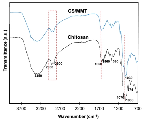
The analysis structure and functional group of chitosan and CS/MMT composite membrane by FTIR spectra are presented in Fig. 1. As seen as the characteristic bands of the pure chitosan membrane which is hydroxyl group, amide I and amide II groups at 3,350 cm−1, 1,650 cm−1 and 1,560 cm−1, respectively.8) The peaks at 2,900 ~ 2,930, 1,390 and 1,030 cm−1 were assigned to –CH2 stretching, –CH2 bending and C–O stretching, respectively.19) Compared with those in the pure CS membrane, the intensity of the hydroxyl group, amide I and amide II bands in the CS/ MMT composite membranes obviously decreases. This phenomenon may be caused by the hydrogen bonds or ionic interaction between the –OH groups on the surface of the montmorillonite and –OH or –NH2 groups of the chitosan. The bands at 1,030 cm−1 in the pure chitosan membrane merge into one and shift to 1,030 cm−1 in the montmorillonite filled membranes due to the overlapping of Si–O band with the C–O stretching band.21) The characteristic bands of PTA shows four peaks at around 1,070, 974, 883 and 823 cm−1 attributed to (P-Oa), (W-Od), (W-Ob-W) and (W-Oc-W,) respectively. This phenomenon indicated that PTA crosslink agent was succesfully make interaction in structure chitosan and CS/MMT composite membrane.4,22-24)
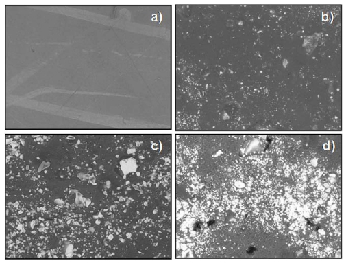
The morphology analysis for chitosan membrane and its composite membrane are presented in Fig. 2. The chitosan membrane shows void-free dense structure. SEM images for CS/MMT 5 and 10 showed good dispersion of MMT filler in the composite membranes. The crosslink technique using PTA was able to increase the compatibility of MMT with chitosan organic polymer, thus produced smooth membrane surface with no or little agglomeration and no pinholes. The absence of pinholes is favourable for the suppression of methanol crossover, thus reduce the methanol permeability of the membrane. However, the CS/MMT membrane with MMT loading 15 wt% have showed visible agglomeration of MMT on the membrane surface. These results were in good agreement with previously reported values for chitosan composites,19) where the agglomeration phenomena most probably due to the excessive loading of MMT filler which did not dissolve properly during membranes solution preparation.
3.2 Performance of CS/MMT Composite Membrane
3.2.1 Water Uptake, Methanol Uptake and Ion Exchange Capacity (IEC)
It is crucial for PEM membrane to be able to hold water because the proton will be transported along the water channel created in the membrane polymer matrix. Thus, high water uptake is favourable for high performance PEM to facilitate great numbers of protons hopping and diffusion through the membrane. The water uptake for CS/MMT membranes is shown in Fig. 3. The water uptake value for pure chitosan membrane is 72.9 %, but as the loading of MMT increased the water uptake decreased. This result should be attributed to possible reasons that the MMT is more hydrophobic than the chitosan. Moreover, the addition of the MMT filler with PTA rigidifies the chitosan chains, resulting in the decrease of their capability to adsorb the solvent molecules. The lowest value occurred in chitosan/MMT 15 wt% which is 46.1%. Similar results have been reported in previous studies,25) that chitosan composite membranes with an increase loading of inorganic fillers showed decreased of water uptake. The reduction of water uptake occurred due to modified MMT agglomeration and the other one is due to intercalation in clay layers which might obstruct the polymer chain movement resulting in chain packing.
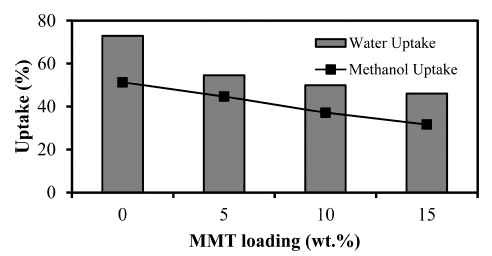
As well as water uptake, methanol uptake is also one of the important properties to determine the quality of the electrolyte membrane, especially in DMFC applications.26) Methanol uptake shows the percentage of membrane properties in absorbing methanol. In a very important operation of a DMFC membrane properties of methanol in order not resist passing into the membrane. If methanol lot of passing into the membrane, it will be able to interfere with the process of fuel cell operation and reduce efficiency. It is therefore highly desirable an electrolyte membrane having a small absorption of methanol. Analysis of methanol uptake of chitosan membranes and CS/MMT composite membrane showed the similar trend with water uptake obtained chitosan membrane at 51.3 %, then decreased after the addition of MMT filler. In the picture also known chitosan membranes have smaller methanol uptake of water uptake. The same observations also has been reported by Yabo Wang et al.,19) where the chitosan composite membranes tend to prefer to absorb water than the methanol.
The effect does not apply to the membrane by addition of MMT filler at various weight, generally indicates that the methanol uptake is higher than the water uptake. The increasing filler is added resulting in a decrease in methanol uptake. This phenomenon indicates that PTA used as a crosslink agent make good interaction between chitosan matrix with the filler.27) The existence of PTA be crosslink bonds make that produces more tightly membrane structure and more inclined to make composite membranes can suppress a little methanol and diffused into the membrane so that it has a low methanol uptake. Most low methanol uptake value of 31.7 % obtained in the composite membrane of chitosan/MMT 15 wt%.
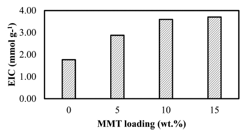
The ion exchange capacity (IEC) for chitosan and CS/ MMT composite membranes shown in Fig. 4. The IEC for pure chitosan is value increased when 5 wt% of MMT was added to the polymer membrane and higher loading of MMT filler has increase the IEC value of CS/ MMT composite membrane. These results are comparable with IEC results for SPEEK/MMT-AMPS composite membrane, reported Mehrab F.S., et al..28) This phenomenon was due to the presence of MMT with PTA crosslink agent to make good interaction with chitosan which provides an opportunity for the ion exchange membrane. One of properties the electrolyte membrane for high performance of fuel cell is ability to exchange ions as a base of move proton in the membrane structure. The IEC highest result in CS/MMT 15, which is 3.71 mmol g−1.
3.2.2 Methanol permeability, proton conductivity, and membrane selectivity
Polymer membrane electrolyte with low methanol crossover is the important factors that must be owned by membrane electrolytes in order to achieve a high performance in DMFC. Membrane must be good morphologies and high mechanical strength to decrease of methanol crossover. The existence methanol molecules in the membrane structure can disturb of polymer electrolyte membrane in fuel cell process.10,11,19) The methanol permeability of pure chitosan and chitosan/MMT composite membranes shown in Table 1. Chitosan membrane shown low methanol permeability, which is 4.97 × 10⁻⁷ cm3/s−2.
Table 1
Methanol permeability, proton conductivity, and relative selectivity of chitosan membrane and CS/MMT composite membranes.
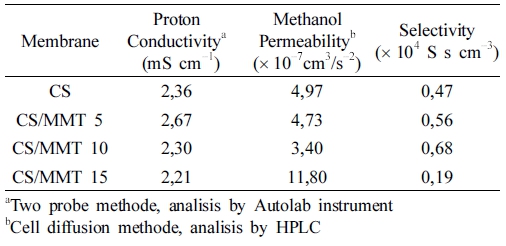 |
The methanol permeability first decreased with loading of MMT 5 wt% and 10 wt%, and occured increasing the methanol permeability when loading of filler increased in CS/MMT 15. This phenomenon in consequence of PTA crosslink agent can be a high interaction with chitosan matrix, so the composite membrane is dense and has ability to suppress of methanol crossover.29,30) But in other cases, the presence of filler increase in the membrane make the spread of interaction not optimally and appear pinholes in the membrane, so the methanol can diffuse into the membrane structure with easily and the methanol permeability increased. The methanol permeability lowest result in CS/MMT 15, which is 3.40 10−7 cm3/s−2.
Table 1 present of the proton conductivity for chitosan and CS/MMT composite membranes and compared with reference. The results show that the optimum loading of MMT filler was able to increase proton conductivity of its composite membrane. In this study, 5 wt% of MMT was the optimum loading to archive maximum proton conductivity of CS/MMT membrane. The CS/MMT 5 was able to increase chitosan membrane proton conductivity from 2.36 mS·cm−1 to 2.67 mS·cm−1. The abundance of –OH group on MMT surface was able to provide additional conduction site for proton to be transported, thus increase the membrane proton conductivity.2,4) However, higher filler loading will introduce the agglomerations problem in CS/MMT membrane, which would reduce the effectiveness of MMT to provide conduction side for proton. In addition, higher MMT loading will reduce membrane water uptake, and since water is crucial for proton conducting, this problem will further decrease the proton conductivity of the membrane.19,31)
The important properties of PEM for DMFC application required to possess both high proton conductivity and low methanol permeability. The Membrane selectivity parameter defined as the ratio of proton conductivity to methanol permeability in the practical usage of PEM in DMFC, which is used as a barometer of membrane electrolyte were has the best proton conductivity with reducing methanol permeability.32-34) The optimal PEM for practical applications commonly considered to decide of selectivity,35) which is high selectivity describes of high performance of membrane electrolyte. The relative selectivity of membrane electrolyte for DMFC could be defined as β = σ/P, where σ and P described the proton conductivity and methanol permeability, respectively.
The membrane selectivity for the composite membrane and pure chitosan listed in Table 1. Compared the pure chitosan membrane, CS/MMT composite membranes exhibits the first increasing and then decreasing trend with the increase of the MMT content. CS/MMT composite membrane with loading of MMT 5 wt% and 10 wt% shown better relative selectivity besides of pure chitosan membrane, and lower values after adding 15 wt% amount of MMT in the biopolymer matrix. This is mainly due to trend of proton conductivity the first increasing and then decreasing, considering support as well as trend methanol permeability the first decreasing and then increasing make results of relative selectivity keep pace with this trend. The membrane selectivity lowest results in CS/MMT 15 which is 0,19 104 S s cm−3 , while the membrane selectivity highest in CS/MMT 10 which is 0,68 104 S s cm−3. The high selectivity of CS/MMT composite membrane implies of high performance for membrane electrolyte which potentially in DMFC application.
4. Conclusion
The composite membrane biopolymer chitosan filled montmorillonite was successfully prepared using solution casting method. The CS/MMT impregnated with phosphotungstic acid (PTA) is developed for the operation of DMFC. The FTIR spectra shows characteristic band of CS, MMT, and PTA indicating was successfully interaction of matrix, filler and additives in composite membrane. SEM images show the MMT was successfully incorporated in chitosan polymer matrix. CS/MMT 5 and 10 show smooth membrane surface, while CS/MMT 15 show visible agglomeration due to undissolved excess MMT. The water uptake for CS/MMT composite membranes was reduced as the loading of MMT increase. The membrane selectivity best results in CS/MMT 10 composite membrane, thus concludes that 10 wt% loading of MMT filler is the optimum loading to improve chitosan membrane characteristics. Considering obtain the high membrane selectivity, low cost, environmentally friendly, easy fabrication, these CS/ MMT implies of high performance for membrane electrolyte which potentially and offer an encouraging promise for DMFC development.
