


1. Introduction
Recently, design and synthesis for lanthanide activated photoluminescence particles have attracted considerable attention in their applications, such as fluorescent lamps, cathode ray tubes, solid-state laser, amplifiers for fiber optics communication and new optoelectronic devices, which show high luminescence quantum yields, since usually more than one metastable excited state exists and multiple emissions are observed.1,2) Rare-earth doped upconversion( UC) particles can convert near infrared radiation of low energy into visible radiation of high energy. The synthesis and the luminescence properties of UC particles have evolved in their applications, since they are considered as potentially active components in new optoelectronic devices and luminescent labels for imaging and biodetection assays, which overcome the current limitations in traditional photoluminescence materials.3)
Most of NaLn(MoO4)2 (Ln = La3+, Gd3+, Y3+) possess the tetragonal scheelite structure with the space group I41/a, and belong to the family of double molybdates compounds. It is stable for the structure of NaLn(MoO4)2 to be transformed to the tetragonal scheelite structure from the monoclinic structure. It is possible for the trivalent rare earth ions in the tetragonal phase to be partially substituted by Ho3+ and Yb3+ ions. These ions are effectively doped into the crystal lattices of the tetragonal phase due to the similar radii of the trivalent rare earth ions, which results in the excellent UC photoluminescence properties.4-6) Among the lanthanide ions, the Ho3+ ion is suitable for converting infrared to visible light through the UC process due to its appropriate electronic energy level configuration. Co-doped Yb3+ ion and Ho3+ ion can remarkably enhance the UC efficiency for the shift from infrared to visible light due to the efficiency of the energy transfer from Yb3+ to Ho3+. The Yb3+ ion, as a sensitizer, can be dramatically excited by an incident light source energy. This energy is transferred to the activator from which radiation can be emitted. The Ho3+ ion activator is the luminescence center of the UC particles, while the sensitizer enhances the UC luminescence efficiency.7-9)
For preparation of the double molybdate NaLn(MoO4)2, several processes have been developed via specific preparation processes, including solid-state reactions,10-13) the sol-gel method,14,15) the Czochralski method,16-19) the hydrothermal method,20-24) the microwave assisted hydrothermal method,25) pulse laser deposition.26) For realized application of UC photoluminescence in products, features such as the homogeneous UC particle size distribution and morphology need to be well defined. Compared with the usual methods, microwave synthesis has advantages of very short reaction time, small-size particles, narrow particle size distribution, and high purity of final polycrystalline samples. Microwave heating is delivered to the material surface by radiant and/or convection heating, which heat energy is transferred to the bulk of the material via conduction.27) It is a cost-effective method that provides high homogeneity and is easy to scale-up, and it is emerging as a viable alternative approach for the quick synthesis of high-quality luminescent materials. However, the NaLa1-x(MoO4)2:Ho3+/Yb3+ phosphors prepared by the microwave sol-gel method have not been reported.
In this study, NaLa1-x(MoO4)2:Ho3+/Yb3+ phosphors with the correct doping concentrations of Ho3+ and Yb3+(x = Ho3+ + Yb3+, Ho3+ = 0.05 and Yb3+ = 0.35, 0.40, 0.45 and 0.50) were successfully prepared by the microwave sol-gel method, followed by heat treatment. The synthesized particles were characterized by X-ray diffraction (XRD) and scanning electron microscopy(SEM). Pump power dependence and Commission Internationale de L'Eclairage(CIE) chromaticity of the UC emission intensity were evaluated in detail. The optical properties were examined comparatively using photoluminescence(PL) emission and Raman spectroscopy.
2. Experimental Procedure
In this study, precise amounts of Na2MoO4·2H2O (99 %, Sigma-Aldrich, USA), La(NO3)3·6H2O (99 %, Sigma- Aldrich, USA), (NH4)6Mo7O24·4H2O (99 %, Alfa Aesar, USA), Ho(NO3)3·5H2O (99.9 %, Sigma-Aldrich, USA), Yb(NO3)3·5H2O (99.9 %, Sigma-Aldrich, USA), citric acid (99.5%, Daejung Chemicals, Korea), NH4OH(A.R.), ethylene glycol(A.R.) and distilled water were used to prepare NaLa(MoO4)2, NaLa0.6(MoO4)2:Ho0.05Yb0.35, NaLa0.55(MoO4)2 :Ho0.05Yb0.40, NaLa0.50(MoO4)2:Ho0.05Yb0.45 and NaLa0.45 (MoO4)2:Ho0.05Yb0.50 compounds with the correct doping concentrations of Ho3+ and Yb3+(Ho3+ = 0.05 and Yb3+ = 0.35, 0.40, 0.45 and 0.50). To prepare NaLa(MoO4)2, 0.2 mol% Na2MoO4·2H2O and 0.114 mol% (NH4)6Mo7O24· 4H2O were dissolved in 20 mL of ethylene glycol and 80 mL of 5M NH4OH under vigorous stirring and heating. Subsequently, 0.4 mol% La(NO3)3·6H2O and citric acid were dissolved in 100 mL of distilled water under vigorous stirring and heating. The molar ratio of citric acid to total metal ions was 2:1. Then, the solutions were mixed together vigorously and heated at 80-100 °C. Finally, highly transparent solutions were obtained and adjusted to pH = 7-8 by the addition of NH4OH or citric acid. To prepare NaLa0.6(MoO4)2:Ho0.05/Yb0.35, the mixture of 0.24 mol% La(NO3)3·6H2O, 0.14 mol% Yb(NO3)3·5H2O and 0.02 mol% Ho(NO3)3·5H2O was used for creation of the solution containing the rare-earth elements. To prepare NaLa0.55 (MoO4)2: Ho0.05/Yb0.40, the solution containing the rareearth elements was employed using 0.22 mol% La(NO3)3· 6H2O, and 0.02 mol% Ho(NO3)3·5H2O and 0.16 mol% Yb(NO3)3·5H2O. To prepare NaLa0.50(MoO4)2:Ho0.05/Yb0.45, the mixture of 0.20 mol% La(NO3)3·6H2O, 0.02 mol% Ho(NO3)3·5H2O and 0.18 mol% Yb(NO3)3·5H2O and was used for the creation of the solution containing the rareearth elements. To prepare NaLa0.45(MoO4)2:Ho0.05/Yb0.50, the solution containing the rare-earth elements was gen erated using 0.18 mol% La(NO3)3·6H2O, and 0.02 mol% Ho(NO3)3·5H2O and 0.2 mol% Yb(NO3)3·5H2O. The transparent solutions were placed into a microwave oven operating at a frequency of 2.45 GHz with a maximum output-power of 1250 W for 30 min. The working cycle of the microwave reaction was controlled very precisely using a regime of 40 s on and 20 s off for 15 min, followed by further treatment of 30 s on and 30 s off for 15 min. The samples were treated with ultrasonic radiation for 10 min to produce a light yellowish transparent sol. After this, the light yellowish transparent sols were dried at 120 °C in a dry oven to obtain black dried gels. The black dried gels were ground and heat-treated at 900 °C for 16 h at 100 °C intervals between 600-900 °C. Finally, white particles were obtained for pure NaLa(MoO4)2 and pink particles were obtained for the doped compositions.
The phase composition of the synthesized particles was identified using XRD (D/MAX 2200, Rigaku, Japan). The microstructure and surface morphology of the synthesized particles were observed using SEM (JSM-5600, JEOL, Japan). The PL spectra were recorded using a spectrophotometer (Perkin Elmer LS55, UK) at room temperature. Pump power dependence of the UC emission intensity was measured at levels of working power from 20 to 110 mW. Raman spectra measurements were performed using a LabRam Aramis (Horiba Jobin-Yvon, France) with the spectral resolution of 2 cm–1. The 514.5- nm line of an Ar ion laser was used as an excitation source; the power on the samples was kept at 0.5 mW level to avoid the sample’s decomposition.
3. Results and Discussion
Fig. 1 shows XRD patterns of the (a) JCPDS 24-1103 pattern of NaLa(MoO4)2, the synthesized (b) pure NaLa (MoO4)2, (c) NaLa0.60(MoO4)2:Ho0.05Yb0.35, (d) NaLa0.55 (MoO4)2:Ho0.05Yb0.40, (e) NaLa0.50(MoO4)2:Ho0.05Yb0.45 and (f) NaLa0.45(MoO4)2:Ho0.05Yb0.50 particles. It was possible to assign almost all of the XRD peaks indexed to pure tetragonal phase, which can be mostly consistent with the standard data of NaLa(MoO4)2 (JCPDS 24-1103). NaLa (MoO4)2 as a member of double molybdate family has a sheelite structure with the lattice constants of a = 5.344 Å and c = 11.730 Å,19) which is tetragonal with space group I41/a. It can be observed, that the diffraction peaks of the doped samples of Fig. 1(c)-(f) shift slightly to the high angle compared to that of pure sample of Fig. 1(b). In the crystal structure of NaLa1-x(MoO4)2, the La3+ ion site is supposed to be occupied by Ho3+ and Yb3+ ions with fixed occupations according to the nominal chemical formulas. The defined crystal structure contains MoO4 tetrahedrons coordinated by four (La/Ho/Yb)O8 square antiprisms through the common O ions. In the doped crystals, the unit cell shrinkage results from the substitution of La3+ ions by Ho3+ and Yb3+ ions. It is assumed that the radiuses of Ho3+(R = 1.015 Å) and Yb3+(R = 0.985 Å) are smaller than that of La3+(R = 1.16 Å), when the coordination number is CN = 8.28) Consequently, it should be emphasized that the Ho3+ and Yb3+ ions can be effectively doped in the NaLa1-x(MoO4)2 lattice by partial substitution of La3+ site, which leads to the unit cell shrinkage due to the similar radii of La3+ and by partial substitution of Ho3+ and Yb3+ while maintaining the tetragonal structure of the NaLa1-x(MoO4)2. Post heattreatment plays an important role in a well-defined crystallized morphology. To achieve a well-defined crystalline morphology, the phases need to be heat treated at 900 °C for 16 h. It is assumed that the doping concentrations of Ho3+/Yb3+ has a suitable effect on the crystalline cell volume maintaining the original structure of the NaLa (MoO4)2.
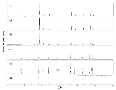
Fig. 1.
X-ray diffraction patterns of the (a) JCPDS 24-1103 pattern of NaLa(MoO4)2, the synthesized (b) pure NaLa(MoO4)2, (c) NaLa0.60(MoO4)2:Ho0.05Yb0.35, (d) NaLa0.55(MoO4)2:Ho0.05Yb0.40, (e) NaLa0.50(MoO4)2:Ho0.05Yb0.45 and (f) NaLa0.45(MoO4)2:Ho0.05Yb0.50 particles.
Fig. 2 provides SEM images of the synthesized (a) NaLa0.60(MoO4)2:Ho0.05Yb0.35 and (b) NaLa0.45(MoO4)2: Ho0.05Yb0.50 particles. The as-synthesized samples are well crystallized with a fine and homogeneous morphology and particle size of 3-5 μm. The samples have no discrepancy in aspect of morphological feature, and agglomerated particles induced by the inter-diffusions among the grains. It should be noted that the doping concentrations for Ho3+ and Yb3+ have no effects on the morphological feature. The microwave sol-gel method of the double moybdates provides the energy to synthesize the bulk of the material uniformly, so that fine particles with controlled morphology can be fabricated in a short time period. The method is a cost-effective way to fabricate highly homogeneous products with easy scale-up and is a viable alternative for the rapid synthesis of UC particles. This suggests that the microwave sol-gel route is suitable for the creation of homogeneous NaLa1-x(MoO4)2:Ho3+/ Yb3+ crystallites.
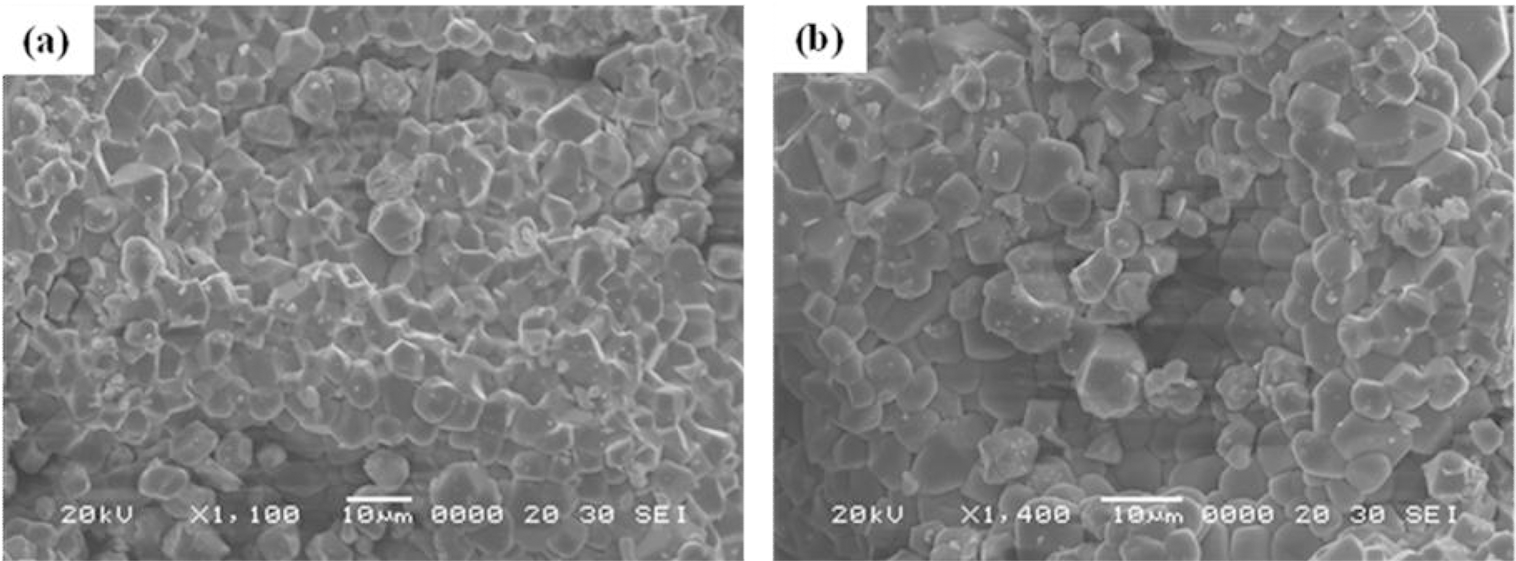
Fig. 2.
Scanning electron microscopy images of the synthesized (a) NaLa0.60(MoO4)2:Ho0.05Yb0.35 and (b) NaLa0.45(MoO4)2:Ho0.05Yb0.50 particles.
Fig. 3 shows the UC photoluminescence emission spectra of (a) NaLa0.60(MoO4)2:Ho0.05Yb0.35, (b) NaLa0.55(MoO4)2: Ho0.05Yb0.40, (c) NaLa0.50(MoO4)2:Ho0.05Yb0.45 and (d) NaLa0.45(MoO4)2:Ho0.05Yb0.50 particles excited under 980 nm at room temperature. The doped samples exhibited strong yellow emissions based on the combination of strong emission bands at 545-nm and 655-nm emission bands in green and red spectral regions, respectively. The strong 545-nm emission band in the green region corresponds to the 5S2/5F4→ 5I8 transition in Ho3+ ions, while the strong 655-nm emission band in the red region appears due to the 5F5→ 5I8 transition in Ho3+ ions. The Ho3+ ion activator is the luminescence center for these UC particles, and the Yb3+ sensitizer dramatically enhances the UC luminescence efficiency. The UC intensity is dependent on the Yb3+: Ho3+ ratio in samples (a) 7:1, (b) 8:1, (c) 9:1and (d) 10:1. The higher intensity of (c) NaLa0.50(MoO4)2:Ho0.05Yb0.45 caused the ratio of Yb3+:Ho3+ to be 9:1, whereas the higher contents of the Yb3+ ion, used as a sensitizer owing to its strong absorption at around 980 nm, can remarkably enhance the UC luminescence through energy transfer.
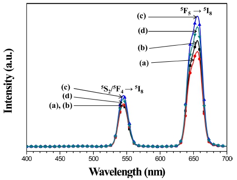
Fig. 3.
The upconversion photoluminescence emission spectra of (a) NaLa0.60(MoO4)2:Ho0.05Yb0.35, (b) NaLa0.55(MoO4)2:Ho0.05Yb0.40, (c) NaLa0.50(MoO4)2:Ho0.05Yb0.45 and (d) NaLa0.45(MoO4)2:Ho0.05Yb0.50 particles excited under 980 nm at room temperature.
The logarithmic scale dependence of the UC emission intensities at 545 and 655 nm on the working pump power over the range of 20 to 110 mW in the NaLa0.50(MoO4)2: Ho0.05Yb0.45 sample is shown in Fig. 4. In the UC process, the UC emission intensity is proportional to the slope value n of the irradiation pumping power, where n is the number of pumped photons required to produce UC emission:29)
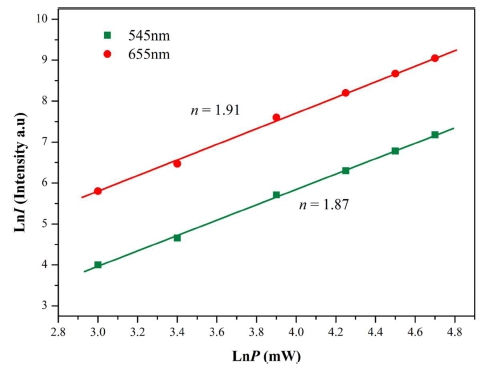
Fig. 4.
Logarithmic scale dependence of the upconversion emission intensity on the pump power in the range from 20 to 110 mW at 545 and 655 nm in the NaLa0.50(MoO4)2:Ho0.05Yb0.45 sample.
Where value n is the number of the pumped photons required to excite the upper emitting state, I is the UC luminescent intensity and P is the laser pumping power. The calculated slope values n in Fig. 4 indicate slope n = 1.87 for green emission at 545 nm; this value is 1.91 for red emission at 655 nm. These results show that the UC mechanism of the green and red emissions can be explained by a two-photon UC process in Er+3/Yb3+ codoped phosphors30) as well as in Ho+3/Yb3+ co-doped phosphors.31)
Based on the results of the analysis of pump power dependence, the known schematic energy level diagrams of Ho3+(activator) and Yb3+(sensitizer) ions in the asprepared NaLa1-x(MoO4)2 samples and the UC mechanisms, accounting for the green and red emissions during 980 nm laser excitation, are shown in Fig. 5. The UC emissions are generated by a two photon process of excited state absorption(ESA) and energy transfer(ET). Initially, the Yb3+ ion sensitizer is excited from the 2F7/2 level to the 2F5/2 level under excitation of 980 nm pumping, and transfers its energy to the Ho3+ ions. Then, the Ho3+ ions are populated from the 5I8 ground state to the 5I6 excited state. This is a phonon-assisted energy transfer process because of the energy mismatch between the 2F5/2 level of Yb3+ and the 5I6 level of Ho3+. Second, the Ho3+ in the 5I6 level is excited to the 5S2 or 5F4 level by the next energy transfer from Yb3+. In addition, the 5S2 /5F4 level of Ho3+ can be populated through the excited state absorption. Finally, the green emission at around 545 nm, corresponding to the 5S2/5F4→ 5I8 transition, takes place. For the red emission, the population of the 5F5 level is generated by two different channels. One channel is the result of Ho3+ in the 5S2/5F4 level state relaxes nonradiatively to the 5F5 level. The other channel is closely related to the 5I7 level populated by non-radiative relaxation from the 5I6 excited state. The Ho3+ in the 5I7 level is excited to the 5F5 level by the energy transfer from Yb3+ and relaxed to the 5F5 level. Therefore, the red emission around 655 nm corresponds to the 5F5→ 5I8 transition.31)
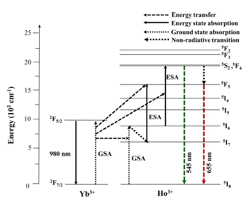
Fig. 5.
The schematic energy level diagrams of Yb3+ (sensitizer) and Ho3+ ions (activator) ions in the NaLa1-x(MoO4)2:Ho3+/Yb3+ system and the upconversion mechanisms of the green and red emissions under 980 nm laser excitation.
Fig. 6 shows the CIE chromaticity diagram for the color coordinates of the NaLa1-x(MoO4)2 phosphors. The inserts indicate the chromaticity points for the samples (a) NaLa0.60(MoO4)2:Ho0.05Yb0.35, (b) NaLa0.55(MoO4)2: Ho0.05Yb0.40, (c) NaLa0.50(MoO4)2:Ho0.05Yb0.45 and (d) NaLa0.45(MoO4)2:Ho0.05Yb0.50 particles. When the concentration ratio of Yb3+:Ho3+ are modulated, the chromaticity coordinate values(x, y) changed. The yellow emission color coordinates of the samples are well matched with the standard equal energy point. This result indicates the achievement of attractive yellow UC emissions for use potentially active components in new optoelectronic devices and luminescent devices.
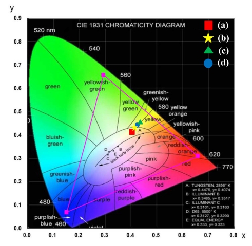
Fig. 6.
CIE chromaticity diagram showing the color coordinates of the NaLa1-x(MoO4)2:Ho3+/Yb3+ phosphors. The yellow emissions for samples (a) NaLa0.60(MoO4)2:Ho0.05Yb0.35, (b) NaLa0.55(MoO4)2:Ho0.05 Yb0.40, (c) NaLa0.50(MoO4)2:Ho0.05Yb0.45 and (d) NaLa0.45(MoO4)2: Ho0.05Yb0.50 are indicated in the insert.
4. Conclusions
UC NaLa1-x(MoO4)2:Ho3+/Yb3+ phosphors with the correct doping concentrations of Ho3+ and Yb3+ were successfully synthesized via the microwave sol-gel route. Well-crystallized particles formed after heat-treatment at 900 °C for 16 h showed a fine and homogeneous morphology with particle sizes of 3-5 μm. Under excitation at 980 nm, the UC doped particles exhibited yellow emissions based on a strong 545-nm emission band in the green region and a very strong 655-nm emission band in the red region, which were assigned to the 5S2/ 5F4→ 5I8 and 5F5→ 5I8 transitions, respectively. The higher intensity of NaLa0.50(MoO4)2:Ho0.05Yb0.45 provided that the ratio of Yb3+:Ho3+ would be 9:1, whereas the higher contents of Yb3+ ion as a sensitizer owing to its strong absorption around 980 nm can remarkably enhance the UC luminescence through energy transfer. The calculated slope values n indicate slope n = 1.87 for green emission at 545 nm; this value is 1.91 for red emission at 655 nm. The yellow emission color coordinates of the samples are well matched with the standard equal energy point. This result indicates the achievement of attractive yellow UC emissions for use potentially active components in new optoelectronic devices and luminescent devices.